System setup and operation – RGBLink VSP 9516S User Manual User Manual
Page 103
6. System Setup and Operation
How to Realize LED Display Connection
VSP 9516S User Manual 103
(9) The setting for port D1 is same as the above setting.
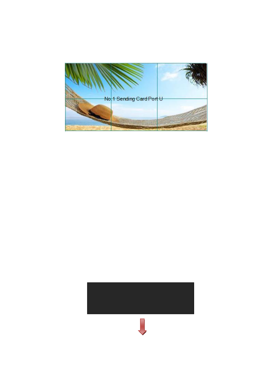
Rendering is as follows:
2. Connect the Port D and Port U of One Sending Card to LED Display
(1) First, make sure the device is in normal operation. The red power indicator lights when
device has power supply and the green signal indicator lights when device has signal
input.
(2) Choose the input signal, for example, choose DVI.
(3) Connect one end of the cable to Port D1, and the other one to U1.
(4) Connect Port U1 of No.1 Sending Card to LED display, the settings are the same as
Step 4 to Step 8 of ―Connect the Port D or Port U of One Sending Card to LED
Display
‖.
(5) Connect Port D1 of No.1 Sending Card to LED display, setting steps are as follows:
a. Turn the knob, choose
knob, choose the sending card type, for example, choose Linsn (VSP 9516S can only
support Linsn and Colorlight sending card). Shown as follows:
>
SENDING CARD TYPE COLOR LIGHT
SENDING CARD NO. NO.1
BRIGHTNESS 50%
QUICK CONNECTION >>