Interface and input signal option, System setup and operation – RGBLink VSP 112U User Manual
Page 80
6. System Setup and Operation
Interface and Input Signal Option
VSP 112U User Manual 80
Interface and Input Signal Option
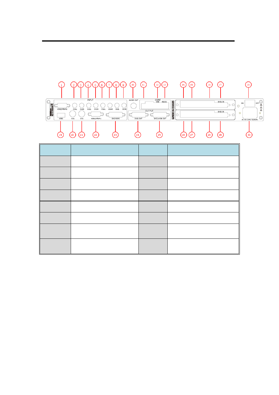
The figure below illustrates the professional interface and control signals of
VSP 112U back panel.
NO
INTERFACE
NO
INTERFACE
2~9
Audio Input RCA port
18
Switch
10
Audio Output BNC port
19
USB input port
11
Dial Switch
20.21
CVBS Input BNC port
12
USB Interface of Device
1.22
VGA Input DB15 port
13
RS232 Interface
23
DVI Input DVI-I
14.15.26.27 10/100M Interface RJ45
24
DVI Output DVI-I
16.28
USB Interface of Sending
Card
25
DVI+VGA DVI-I Output
17.29
DVI Input Port of Sending
Card
30
Power IEC-3 port
24. DVI1 is default the main image output , use for connecting the sending
card of LED display, VSP 168S supports resolution format as following:
800x600x60Hz, 1024x768x60Hz, 1024x768x75Hz, 1280x720x60Hz,
1280x720x50Hz, 1280x768x60Hz, 1280x800x60Hz, 1280x1024x60Hz,
1360x768x60Hz, 1366x768x60Hz, 1400x1050x60Hz, 1440x900x60Hz,
1600x1200x60Hz,1680x1050x60Hz,1920x1080x60Hz,1920x1080x50Hz,
1920x1200x60Hz, 2048x1152x60Hz, 2560x812x60Hz, 2560x816x60Hz.
25. DVI2 + VGA output, output DVI video signal or VGA video signal,