Vsp 112u back panel, Cont interface, Dial switch – RGBLink VSP 112U User Manual
Page 26: Usb interface, Hardware orientation, Cont interface 11: dial switch
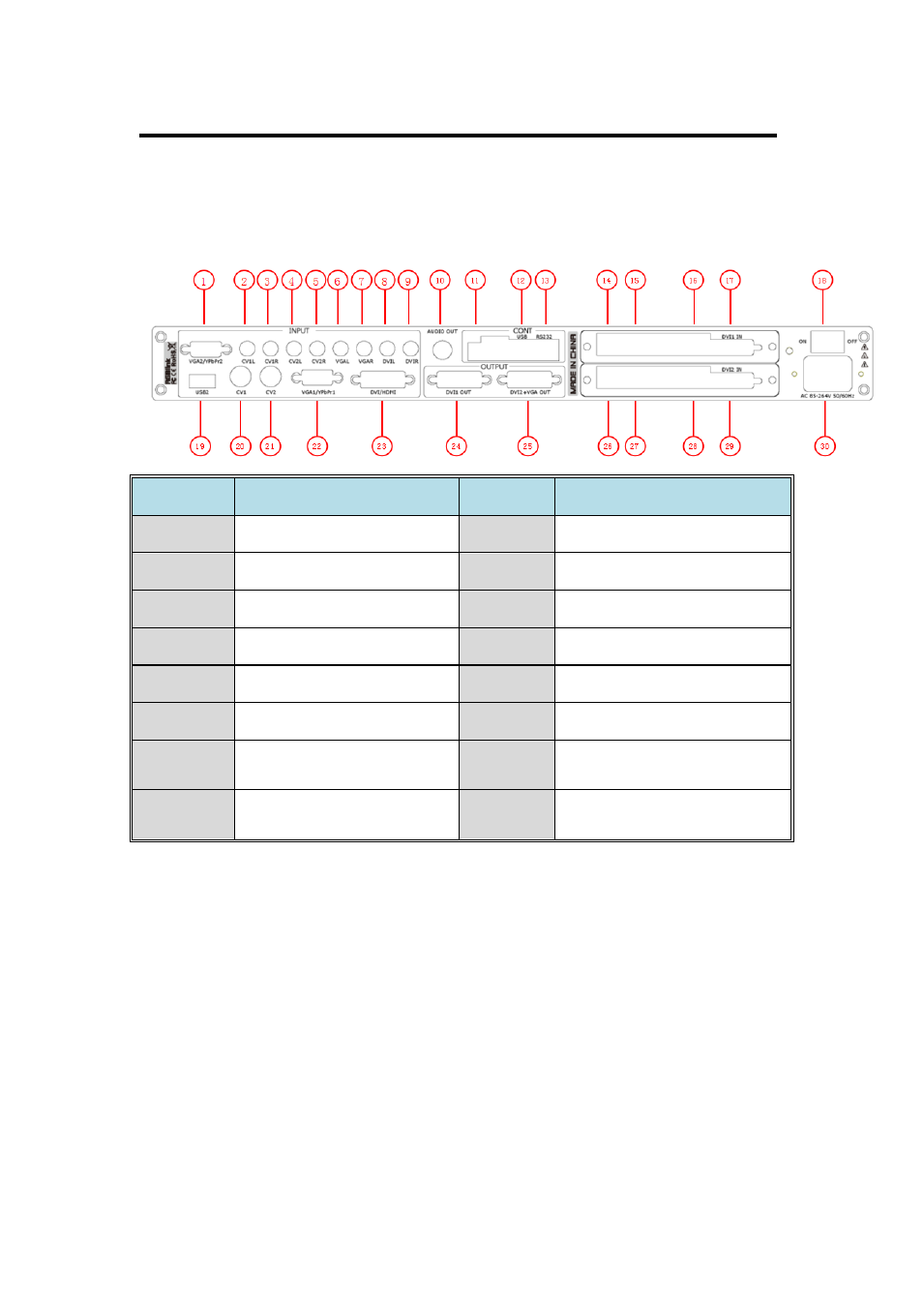
2. Hardware Orientation
VSP 112U Back Panel
VSP 112U User Manual 26
The figure below illustrates the professional interface and control signals of
VSP 112U back panel.
NO
INTERFACE
NO
INTERFACE
2~9
Audio Input RCA port
18
Switch
10
Audio Output BNC port
19
USB input port
11
Dial Switch
20.21
CVBS Input BNC port
12
USB Interface of Device
1.22
VGA Input DB15 port
13
RS232 Interface
23
DVI Input DVI-I
14.15.26.27 10/100M Interface RJ45
24
DVI Output DVI-I
16.28
USB Interface of Sending
Card
25
DVI+VGA DVI-I Output
17.29
DVI Input Port of Sending
Card
30
Power IEC-3 port
CONT Interface
11: Dial Switch
If the two dial switches are upwards, the device is in normal work, and if
they are downwards, the device is in upgrade state. OLED module light is
off when the device is in upgrade state. Some of the button lights turn on,
and the device will not work.
12: USB Interface