REMKO GPM User Manual
Page 7
7
The advantages of the units
lie in the modular mode of
operation, meaning the heat
output created and thus the gas
flow (consumption of fuel) are
changed corresponding to the heat
requirement.
With a reduced heat requirement
of the room, the fan-assisted
heater consumes less fuel,
whereby its efficiency is increased
by up to 94%.
Intrinsic safety
The increase in efficiency with
minimum output is achieved
through the use of a modern air/
gas mixture technology and the
simultaneous flow rate regulation
of combustion air and gas.
This technology increases the
safety of the equipment, because
the gas valve feeds the fuel
depending on the amount of air
in accordance with its factory
settings.
Unlike atmospheric burners, the
CO
2
content remains the same
through the entire operating range
and allows an increase in efficiency
with reduction of the heat output.
With no combustion air, the
valve does not release gas. With
reduction of the combustion
air, the gas valve automatically
reduces the amount of gas and
keeps the combustion parameters
at an optimal level.
Minimal pollutant emissions
The premix burner provides for
"clean" burning with low pollutant
emissions with the air/gas valve.
Efficiency
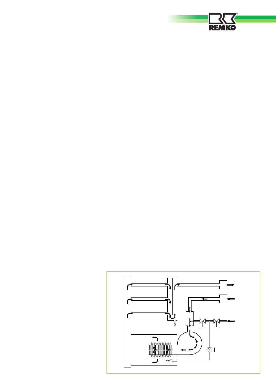
Cycle of operation
Burner operation
The heat requirement for starting
the burner can be adjusted with
the room temperature sensor
NTC2 in the electronic temperature
regulation ATR-6.
In the cases of equipment both
with and without electronic
temperature regulation, the burner
is only started if the contact 7-9 of
the terminal block M1 is closed.
At the beginning, while igniting,
the control PCB starts the fan of
the burners so that the combustion
chamber is pre-ventilated for a
pre-adjusted length of time. After
the pre-ventilation, the control
PCB releases the flame monitoring
unit ACF for ignition of the burner.
Then the gas-solenoid valve EV1
and solenoid valve EVP, which
supply the ignition gas burner, are
then opened.
In this way the ignition burner's
ignition phase, which takes place
through the ignition electrode, is
started.
The monitoring electrode, on the
other hand, checks the successful
ignition of the gas flame.
If this operational condition is
recognised, the control device
opens the main gas valve EV2 for
the supply of the actual burner.
After a certain length of time,
during which both burners
(ignition burner and main burner)
are simultaneously in operation,
the control PCB switches off
the electromagnetic valve EVP,
whereupon the ignition burner
extinguishes.
The flame monitoring for the
control of the main burner likewise
takes place through the monitoring
electrode.
The startup program switches on
the burner with an average heat
flow rate, which is set to about
70%of the highest flow rate.
Approximately thirty seconds after
the ignition, the burner starts
with the modulation of the gas
flow rate and then achieves the
gas flow rate determined by the
settings.
During operation, the control
PCB regulates the gas flow rate
of the burner proportional to the
circulating air temperature, which
is measured by the NTC1 sensor
on the rear side of the unit.
Luft
Abgase
Gas
EV1
EV2
EVP
HW080909