Remko gpm, Electrical connection – REMKO GPM User Manual
Page 28
28
REMKO GPM
Electrical connection
The electrical connection of the
unit may only be carried out by
authorised technicians (electrical
power company-approved) in
accordance with the applicable
regulations.
A main/emergency shutoff switch
should be installed in an easily
accessible position on the visible side
of the unit and protected against
unintended actuation. The switch
must disconnect all poles from
the unit with a minimum contact
opening of 3 mm from the mains.
The main/emergency shutoff
switch may only be used in
emergency situations or with
extended periods of non-use.
If it is switched off during
the operation of the unit,
the electrical supply-air fan
cannot cool the combustion
chamber. This can result in
damage to the unit.
ATTENTION
A multipolar isolator with
appropriate electrical
protection must be connected
upstream to the units.
The wire cross-section must
be at least 1.5 mm².
ATTENTION
The units may only be connected
to the mains through outlets/plugs
with reverse polarity protection.
Electrical supply 230/1~/50,
Minimum cross-section of the
mains supply 1.5 mm².
NOTE
Phase and neutral lines may
absolutely not be
interchanged during
connection, because the
flame monitoring device
will otherwise interrupt unit
operation for safety reasons.
Fault F1 is displayed.
NOTE
The use of a multipolar
wire that serves for both
the electronic temperature
regulation and power supply is
not permitted for avoidance of
electromagnetic disturbances.
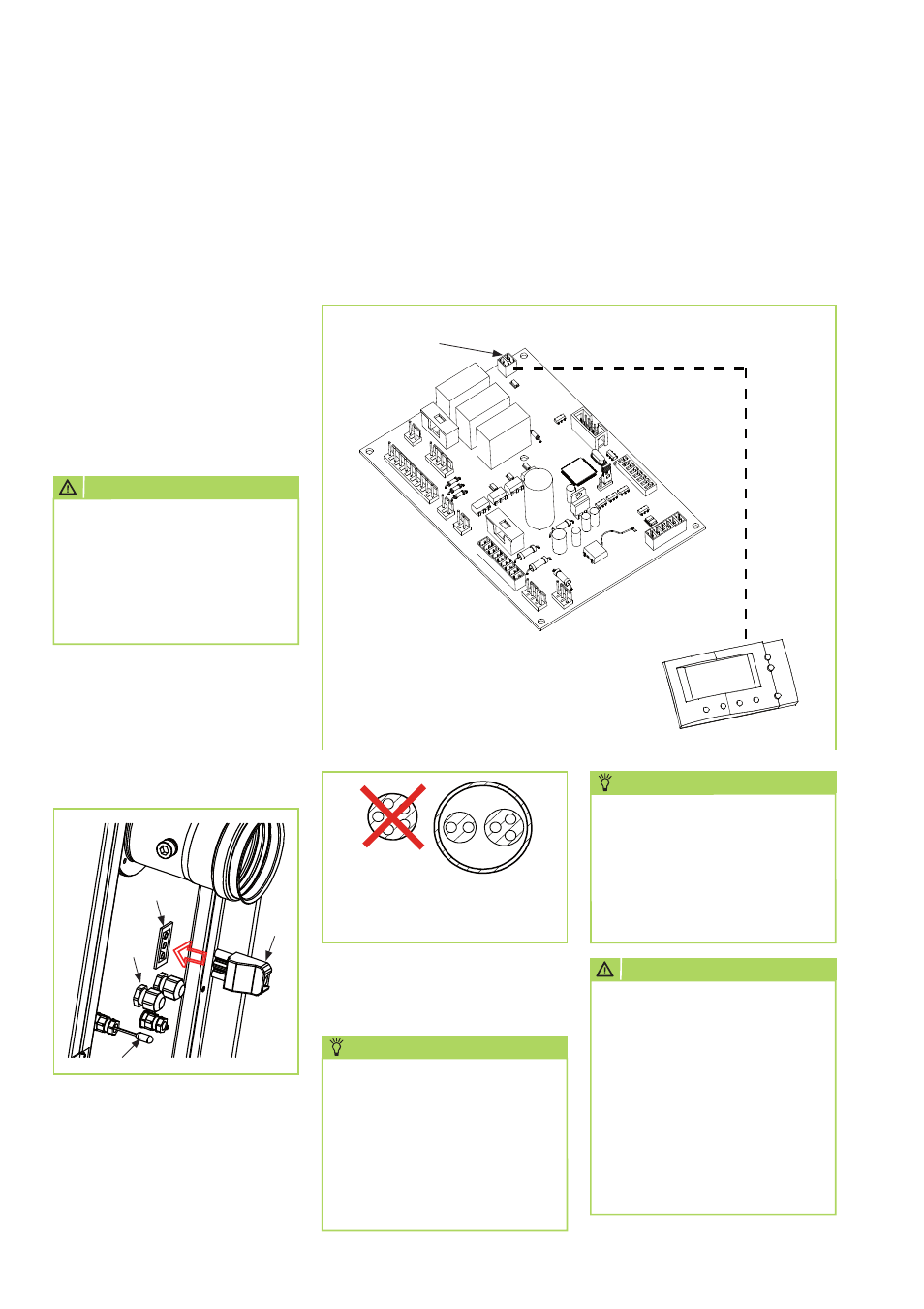
Rear panel legend:
= Unit power outlet
= Unit plug
= Cable guides
= Unit temperature sensor
Electronic temperature regulation ATR-6 connection to the control PCB
Connect the plug of the electronic temperature regulation to the
customer-installed bus cable, pull out the 2-pole plug connector [CN]
with resistor from the control PCB and re-connect the installed plug with
bus cable.
Electronic temperature
regulation ATR-6
Control PCB
Plug CN
JA
NEIN!
B
L
B = Bus cable
S = live cable
We reserve the right to modify the dimensions and constructional design as part of the ongoing technical development process.