Electrical circuit diagram – REMKO ML 262 DC Arctic User Manual
Page 23
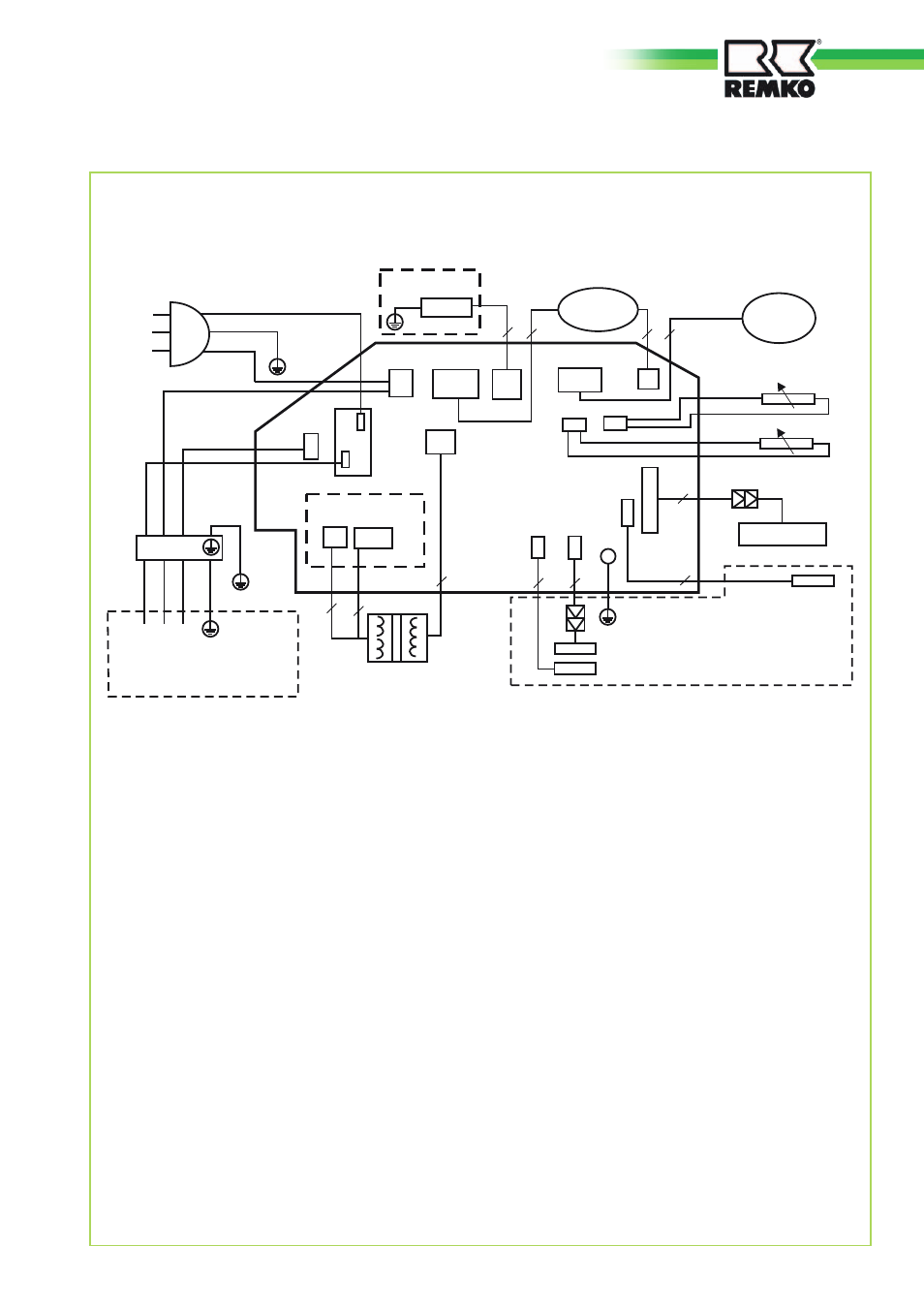
Electrical circuit diagram
ML 262-522 DC IT
S
N
L
Y/G
CN3
S
Y/G
3
4
RY1
CN6
CN5
CN1
N
CN12
CN8
CN11
CN9
CN7
3
2
2
4
L N S
JX1
I ON
2
3
CN4
CN14
CN13
CN10
P_1
3
7
2
2
5
CN
2
CN
17
F1 = Manual On/Off
Manual On/Off
to outdoor component
M1 = Swing motor
M2 = Fan motor
T1 = Transformer
S1 = Air circulation sensor
S1
S2
S2 = Vaporiser sensor
V1 = Board display
Display
M1
T1
M2
23
This manual is related to the following products: