Remko ml...dc - arctic, Electrical circuit diagram, Uv w – REMKO ML 262 DC Arctic User Manual
Page 22
N
U
V
~
~
~
~
+
+
-
-
Y/G
3
4
7
9
7
FILTER
H
L1 L
H
2
H
1
N
H
2
N
N
L
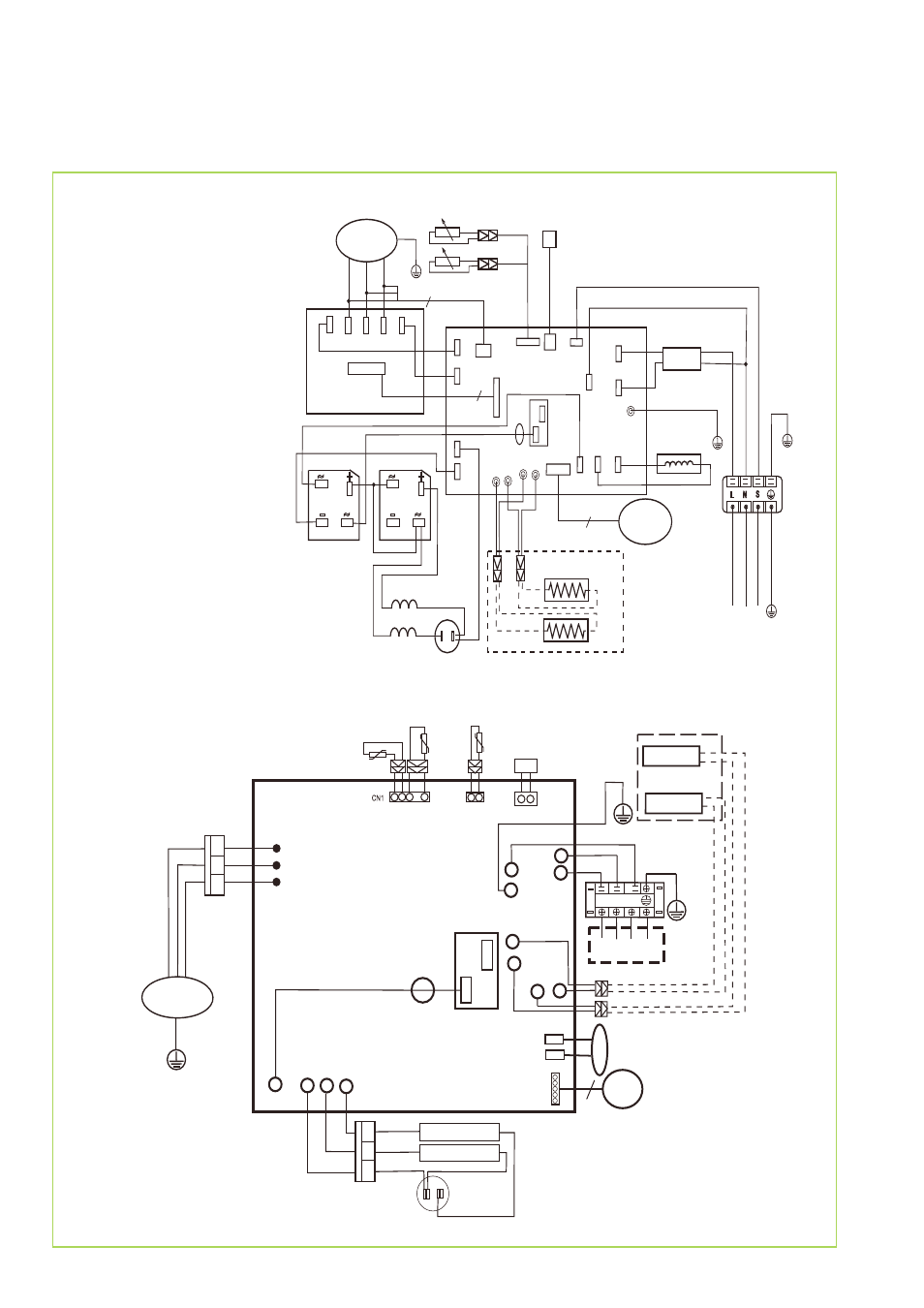
Electrical circuit diagram
ML 262-352 DC AT
F1 = Condenser fan
C1 = Compressor
C1
C1
GL
GL
GL
ST
LP = Power board
ST = Control board
GL = Rectifier
S1 = Condenser feeler
S1
S2
S2 = Air-intake sensor
S3 = Heated gas sensor
S4 = Compressor sensor (Klixon)
V1
V1
F1
F1
V1 = Reverse flow valve
U
V
CN7
CN28
CN26
CN
10
N-
B
CN
3
CN
2
CN14
CN4
N S
L
CN31 CN33
CN34
U
V
W
CN6
6
ML 522 DC AT
REMKO ML...DC - ARCTIC
22
This manual is related to the following products: