REMKO ML 262 DC Arctic User Manual
Page 19
Supplementary information
for Installation
■
If the basic length of the
refrigerant line exceeds
5 m, add refrigerant when
commissioning the system for
the first time. (See chapter
"Add refrigerant").
Only use tools and compo-
nents designed for refrigera-
tion applications.
NOTE
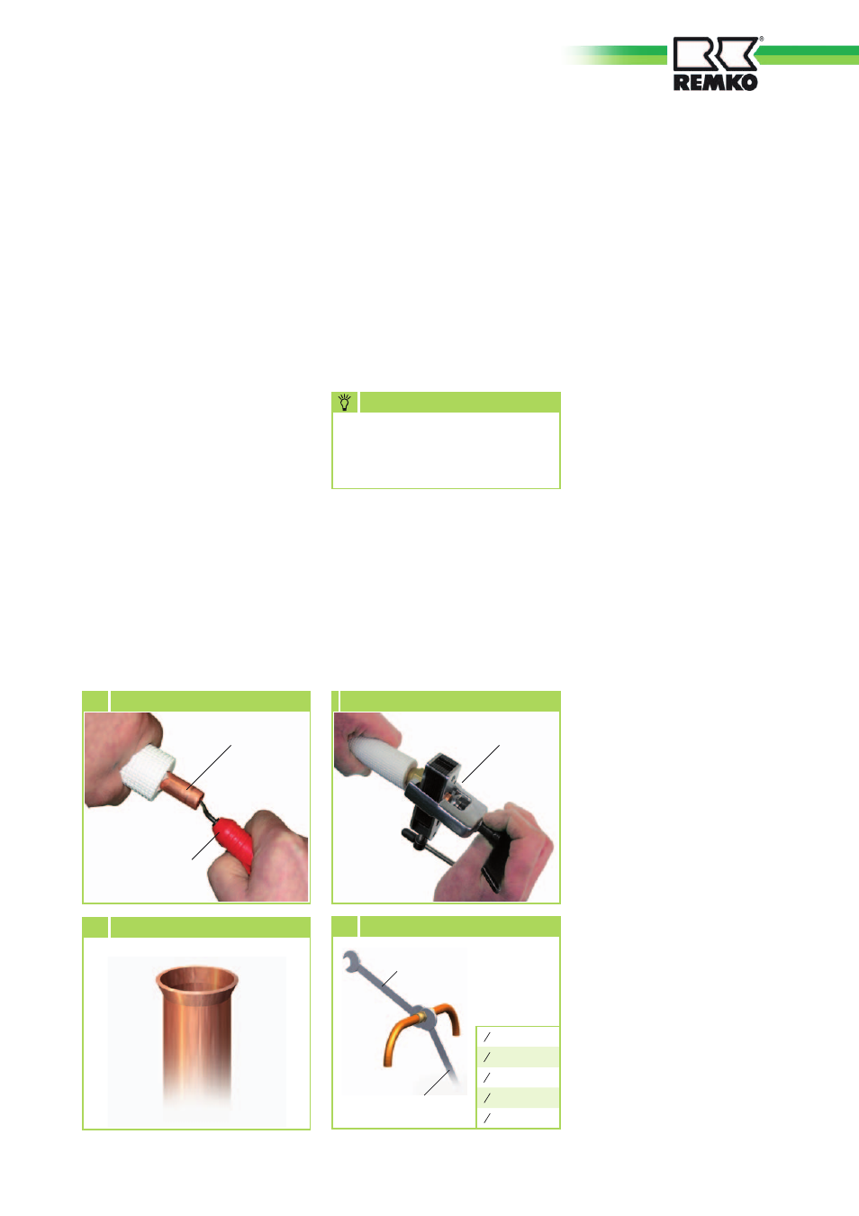
Flanging tool
7 Flanging the refrigerant line
Refrigerant line
Deburrer
6 Deburring the refrigerant line
8 Correct flange shape
Tighten 1st Spanner
Counter
2nd Spanner
9 Tighten fittings
Tightening
torque:
1 4
“ 15-20 Nm
3 8
“ 33-40 Nm
1 2
“ 50-60 Nm
5 8
“ 65-75 Nm
3 4
“ 95-105 Nm
5. Verify that the shape of the
flange is correct(figure 8).
6. First connect and hand-tighten
the refrigerant connections
to ensure they are correctly
seated.
7. Now fully tighten the fittings
using 2 suitably sized open-
ended spanners. Use one
spanner to counter the force
when tightening the fitting
(figure 9)
.
8. Use only diffusion-tight
insulation hoses designed for
this temperature range.
9. Lay the refrigerant lines from
the indoor unit to the outdoor
component. Ensure that they
are adequately fastened and
take measures for the oil return,
if necessary!
10. During installation, observe
guidelines on the permitted
bending radius for the
refrigerant lines and never bend
a line twice in the same place.
Brittleness and cracking can
result.
12. Ensure that structure-borne
sound is not transferred to
the building. Use vibration
dampers to reduce the effects
of structure-borne sound!
13. Prepare the refrigerant lines
for the outdoor component as
described above.
11. Use the wall or floor brackets to
fasten the outdoor component
where structurally allowed
(refer to the installation
instructions for the brackets).
19