Component & system wiring 78, Gbd device oe210 space temperature sensor – Orion System VCM Component User Manual
Page 78
Component & System Wiring
78
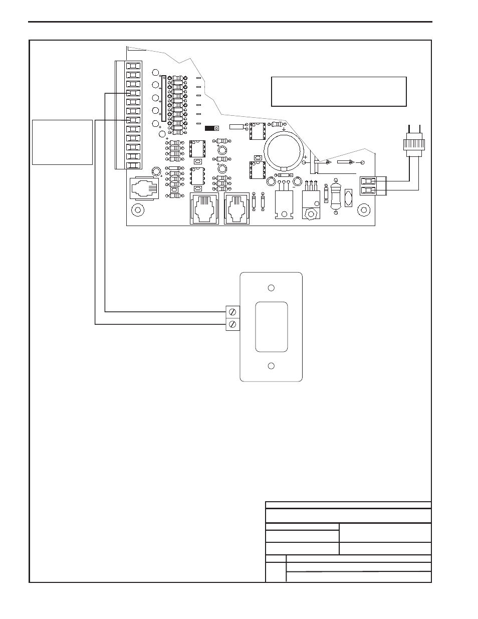
GBD Controller - Space Temp. Sensor Averaging Wiring (Cont’d)
FILENAME
DATE:
B. CREWS
DESCRIPTION:
PAGE
DRAWN BY:
JOB NAME
FILENAME
JOB NAME
4 of 5
OE331-21- AVG
GBD Device Wiring
Line
V
olt
age
GBD Device
OE210 Space Temperature Sensor
24VAC
GND
Up to (6) Temperature Sensors
Can Be Used On The GBD.
AIN2, AIN3, AIN4,
They Can Be Wired
To AIN1,
AIN5 And AIN7 As
Desired.
Typical Wiring
Shown For Input
AIN3. Wiring For
Other Inputs Is
Identical.
POWER
VR2
TB4
VR1
PJ3
PJ2
PJ1
EXPANSION
PRESSURE
T'STAT
SENSOR
C17
D15
C20
D17
D6
D7
D8
D9
D11
D14
C12
C10
0-5
VDC
0-1
VDC
JP1
X2
TB3
INPUTS
+VDC
AOUT1
AOUT2
AIN7
AIN5
AIN4
AIN3
AIN2
AIN1
RN5
C4
CX15
PU1
PU2
PU3
PU4
PU5
GND
GND
PU7
GND
OE331-21-AVG
GBD Device Wiring
When Used For Space Temperature Sensor Averaging Applications
GND
TMP
2.) 24 VAC Must Be Connected
So That All Ground Wires
Remain Common.
Notes:
4.) All Wiring To Be In Accordance
With Local And National Electrical
Codes And Specifications.
3.) Set-up, Programming And
Monitoring Of The GBD Device
Requires The Use Of A Personal
Computer And Prism Software.
1.) The GBD Can Either Be Used
With CO2 Sensors Or Space
Temperature Sensors But Not
Both On The Same GBD Device.
Up to 2 GBD Devices Can Be
Located On Each Local Loop.
Warning
:
24 VAC Must Be Connected So That All Ground
Wires Remain Common. Failure To Do So Will
Result In Damage To The Controllers.
24 VAC Transformer
20VA Minimum
10/07/05
OE331-21-AVG-GBD-Wire1A.CDR