Vav/zone controller board wiring, Component & system wiring 52, Airflow probe – Orion System VCM Component User Manual
Page 52: Component wiring diagram
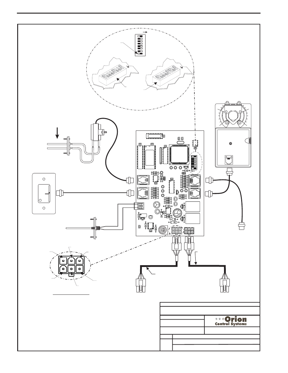
Component & System Wiring
52
Notes:
1
0
Locate In Supply Duct
Near Zone Damper
Zone Actuator
Supply Air
Temperature
Sensor
Pin Layout Diagram
VAV/Zone Controller Board
Room Sensor
(See Note 3)
3.)The Supply Air Sensor is not required when the VAV/Zone Controller is
connected to an Orion VAV/CAV or VCM Unit Controller board. A global
supply air temperature is broadcast by the VAV/CAV or VCM Unit
Controller. The Supply Air Sensor is only required if the VAV/Zone
Controller is required to operate as a “Stand Alone” controller.
1.) All wiring to be in accordance with local and national electrical codes
and specifications.
2.) All communication wiring to be 2 conductor twisted pair with shield.
Use Belden #82760 or equivalent.
NORMAL
OVR
R
E
L
O
C
R
E
M
R
O
A
W
ACTUA
T
O
R
EXP
ANSION
NET
ADD
8
32
16
2
4
1
SW1
U9
PJ4
AIRFLOW
SP
ACE
SENSOR
PJ3
R25
TB2
AIN
GND
P2
P1
P1
PJ2
PJ1
Hi
Lo
Airflow
Airflow Probe
(For Pressure Independent Applications Only)
Power/Comm Cable To
Next VAV/Zone Controller or
Power/Comm Distribution Board
Power/Comm Cable
From Power/Comm Distribution Board
Or Previous VAV/Zone Controller
(GR) GND
(RD) 24 VAC
(WH) T
(Bare) SHLD
(BK) R
(BR) GND
FILENAME
DATE:
B. Crews
DESCRIPTION:
PAGE
DRAWN BY:
Component Wiring Diagram
JOB NAME
05/18-06
O-VAV-ZoneWire1.CDR
OE324-00-VAVZ Orion VAV/Zone Controller
16
32
TOKEN
NET
8
4
2
1
Address Switch Shown Is
Set For Address 9
Address Switch Shown Is
Set For Address 13
Controller
Address Switch
This Switch Must Be
In The ON Position
As Shown
ADDRESS
ADD
ADD
RES
S
ADD
ADD
RES
S
ADD
The Address For Each Controller
Must Be Between 1 And 58 And Be
Unique To The Other Controllers
On The Local Loop
To Optional Relay
Expansion Board
1 of 1
VAV/Zone Controller Board Wiring