Modular service tool connections, Component & system wiring 61, Power on button – Orion System VCM Component User Manual
Page 61
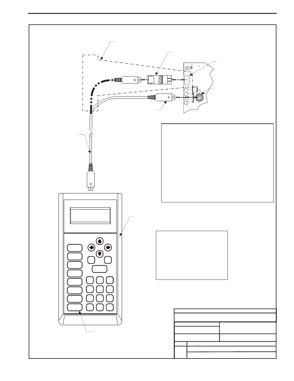
Component & System Wiring
61
FILENAME
DATE:
B. Crews
DESCRIPTION:
PAGE
DRAWN BY:
Connection Diagram
JOB NAME
02/11/04
G-ModServiceTool1A.CDR
OE391 Modular Service Tool
1 of 1
Typical Controller Board
Connector Cable
Modular Service Tool
Female DIN Connector
T
Block Base
erminal
(Remove Terminal Block)
PL101904 Adapter Board
Optional Connection For
Controllers Without DIN Connector
Male DIN Connector
Mode
Selection
ENTER
CLEAR
ESC
PREV
NEXT
DOWN
UP
6
5
4
DEC
7
0
8
1
3
2
9
MINUS
-
STATUS
SETPOINTS
SCHEDULES
CONFIGURATION
ALARMS
ON
OVERRIDES
BALANCE - TEST
Be Sure The Modular Service
Tool Is Connected To The
Supplied Power Pack Or Has
Fresh Batteries Installed Before
Attempting Programming Of The
Controller. Be Sure The Power Is
Turned Off On The Modular
Service Tool Before Connecting
The Cable To The Controller.
The Modular Service Tool Can Be Connected To Most
Controllers By Plugging One End Of The Supplied
Cable Into the Modular Service Tool DIN Connector
And The Other End Into The DIN Connector On The
Controllers.
Some Controllers Without DIN Connectors Require
Use Of The Supplied PL101904 Adapter Board Shown
Above. To Connect With Adapter Board, First Unplug
COMM Terminal Block From Controller Board. Plug
PL101904 Adapter Board Terminal End Into Terminal
Block Base On Controller. Plug DIN Connector Cable
Into DIN Connector On PL101904 Adapter Board . See
Optional Connection For Controllers Without DIN
Connector Above For Illustration Of This Connection.
Power On Button
T
SHLD
R
COMM
Modular Service Tool Connections