Interconnected - computer connection with ip-link, Component & system wiring 11 – Orion System VCM Component User Manual
Page 11
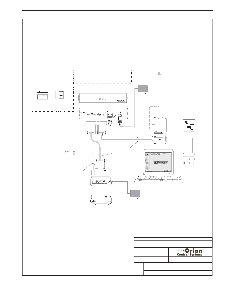
Component & System Wiring
11
Connect To HVAC Unit Controller
See Page 1 Of This Drawing For Wiring
9 Pin
Female
End
Connect Ethernet
RJ45 Cable
Assembly
To 10BaseT Port
On IP-Link
9 Pin
Female
Connector
9 Pin
Female
Connector
Molded
Cable Assembly
Supplied With
IP-Link Kit
9 Pin Male End
Connect To Serial
Port On IP-Link
25 Pin
Female
Connector
(If Reqd)
Connect To Computer
Serial Port
Personal Computer
(By Others)
Connect Ethernet RJ45
Cable Assembly
(By Others)
To 10 BaseT Connection
On Ethernet Router
Or Modem
(By Others)
Back View of CommLink
Back View of IP-Link
Note: CommLink Is Only Required If Alarm Callout,
Remote Computer Connection Or Direct Computer
Connection To System Is Desired. IP-Link Is Only
Required If E-mail Alarm Notification Or Remote
Computer Connection Is Required.
Front View of IP- Link
C
L
II
omm ink
LOOP
24V
T G R
GND
REMOTE LINK
(DTE)
COMPUTER
(DCE)
485
LOOP
STATUS
POW
ER
COMP
RLINK
SERIAL #
C
O
N
T
R
O
L
S
8 Conductor
Modular Cable
Assembly
110 VAC To
9 VDC
Power Pack
110 VAC To
24 VAC
Power Pack
IP-Link
(Optional)
SHLD
T
R
Typical Terminal Blocks. All
Wiring To Be T To T, SHLD (G)
To SHLD (G) & R To R
T G R
485
LOOP
Optional Computer Connection Diagram
Using IP-Link For Remote Connection
Front View of CommLink
CommLink
Note:
1.Set CommLink Internal Switch To “Single”.
2. Replace CommLink EPROM With IP-Link
EPROM Supplied With IP-Link Kit
9VDC
10BaseT
Serial
Mode
PWR
S
E
R
R
C
V
LN
K
A
C
T
Connect ne
Notes:
1.) All wiring to be in accordance with local and national electrical codes
and specifications.
FILENAME
DATE:
B. Crews
DESCRIPTION:
PAGE
DRAWN BY:
Wiring & Connection Diagram
JOB NAME
06/20/03
O-System-Interconnected.CDR
Interconnected System
3 of 3
Interconnected - Computer Connection With IP-Link