Binary input board wiring, Component & system wiring 41, Vcm controller wiring detail – Orion System VCM Component User Manual
Page 41
Component & System Wiring
41
FILENAME
DATE:
B. Crews
DESCRIPTION:
PAGE
DRAWN BY:
JOB NAME
OVCM-BinInput-Brds-Wr-1A.CDR
1 of 1
03/06/06
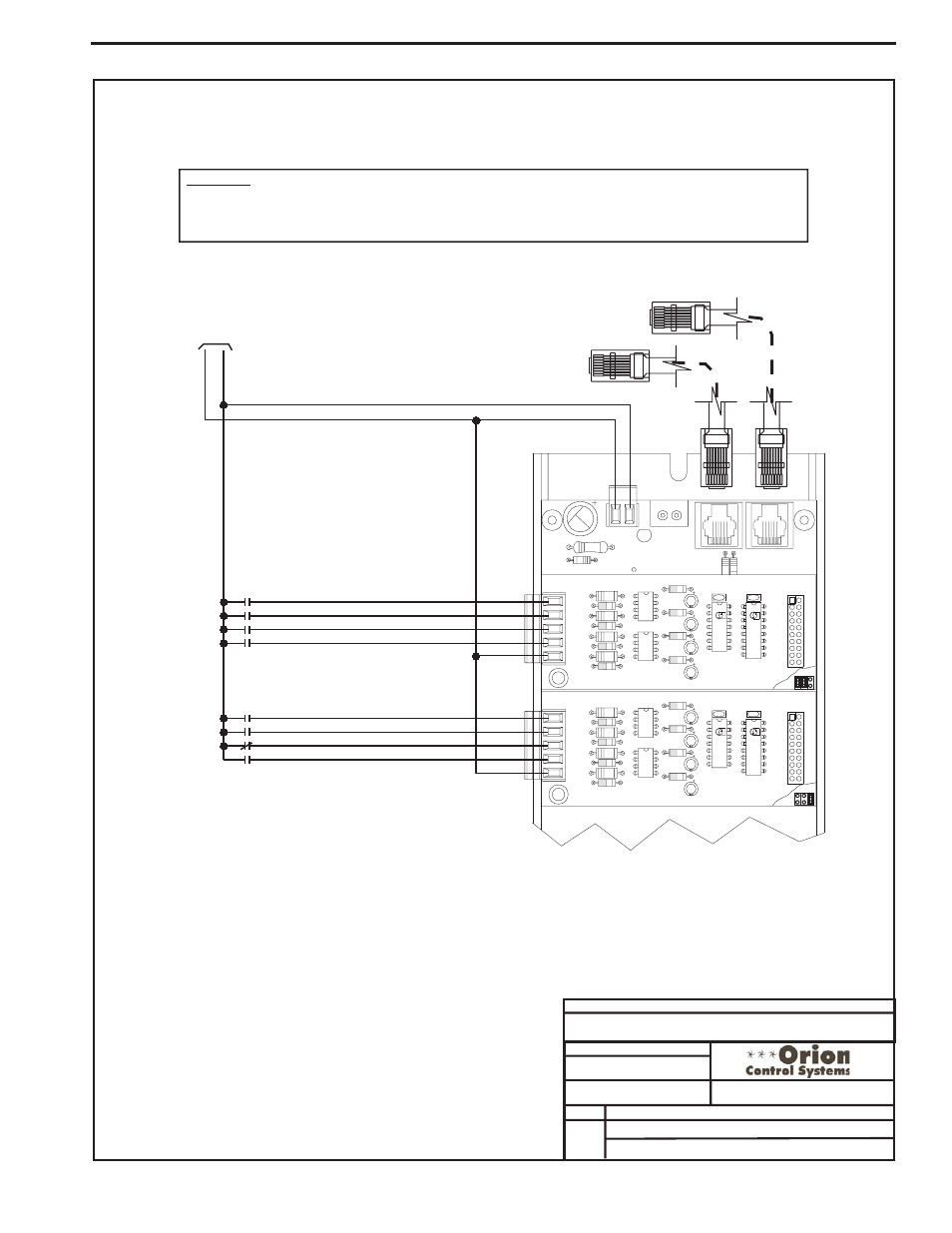
VCM Controller Wiring Detail
Binary Input Expansions Boards
R20
C8
TB2
D3
PWR LD1
24V
AC-IN
GND
GND
TB1
PJ2
+24VDC-OUT
R17
PJ1
R15
R4
R3
R2
R1
YS101788
BIN 4
BIN 3
BIN 2
BIN 1
COM
TB1
OPTO2
R10
R12
4 DIG. IN MOD. I/O BD.
P2506-2
R8
R6
R5
P2506-2
OPTO1
74HC14N
PCF8574P
U2
C4
C3
U1
CX2
C2
C1
CX1
P1
R4
R3
R2
R1
YS101788
BIN 4
BIN 3
BIN 2
BIN 1
COM
TB1
OPTO2
R10
R12
4 DIG. IN MOD. I/O BD.
P2506-2
R8
R6
R5
P2506-2
OPTO1
74HC14N
PCF8574P
U2
C4
C3
U1
CX2
C2
C1
CX1
P1
OE356
-4
Binary
Input
Board
#1
OE356
-4
Binary
Input
Board
#2
Remote Forced Heating - N.O. Contact
Remote Forced Cooling - N.O. Contact
Hood On - N.O. Contact
Dirty Filter - N.O. Contact
Proof Of Flow - N.O. Contact
Remote Forced Occupied - N.O. Contact
Smoke Detector - N.C. Contact
Remote Forced Dehumidification - N.O. Contact
COM
BIN4
BIN3
BIN2
BIN1
COM
BIN3
BIN4
BIN1
BIN2
Modular Cable
Connect To VCM Controller
Modular Cable
Connect To Next Expansion Board
(When Used)
24
V
A
C
GND
OE352 2 Slot Or OE353 - 4 Slot Expansion Board
As Required
10 VA Minimum Power Required For
Each OE352 - 2 Slot Expansion Base
Board. 20 VA Minimum Power
Required For Each OE353 - 4 Slot
Expansion Base Board
WARNING!!
Observe Polarity! All boards must be wired with GND-to-GND and 24VAC-to-24VAC. Failure to observe polarity will result
in damage to one or more of the boards. Expansion Boards must be wired in such a way that power to both the
expansion boards and the controller are always powered together. Loss of power to the expansion board will cause the
controller to become inoperative until power is restored to the expansion board.
Binary Input Board Wiring