Supply fan vfd & bypass damper actuator wiring, Component & system wiring 37 – Orion System VCM Component User Manual
Page 37
Component & System Wiring
37
FILENAME
DATE:
B. Crews
DESCRIPTION:
PAGE
DRAWN BY:
JOB NAME
OVCM-ZoneByp-SFVFD-Wr1A.CDR
1 of 1
03/06/06
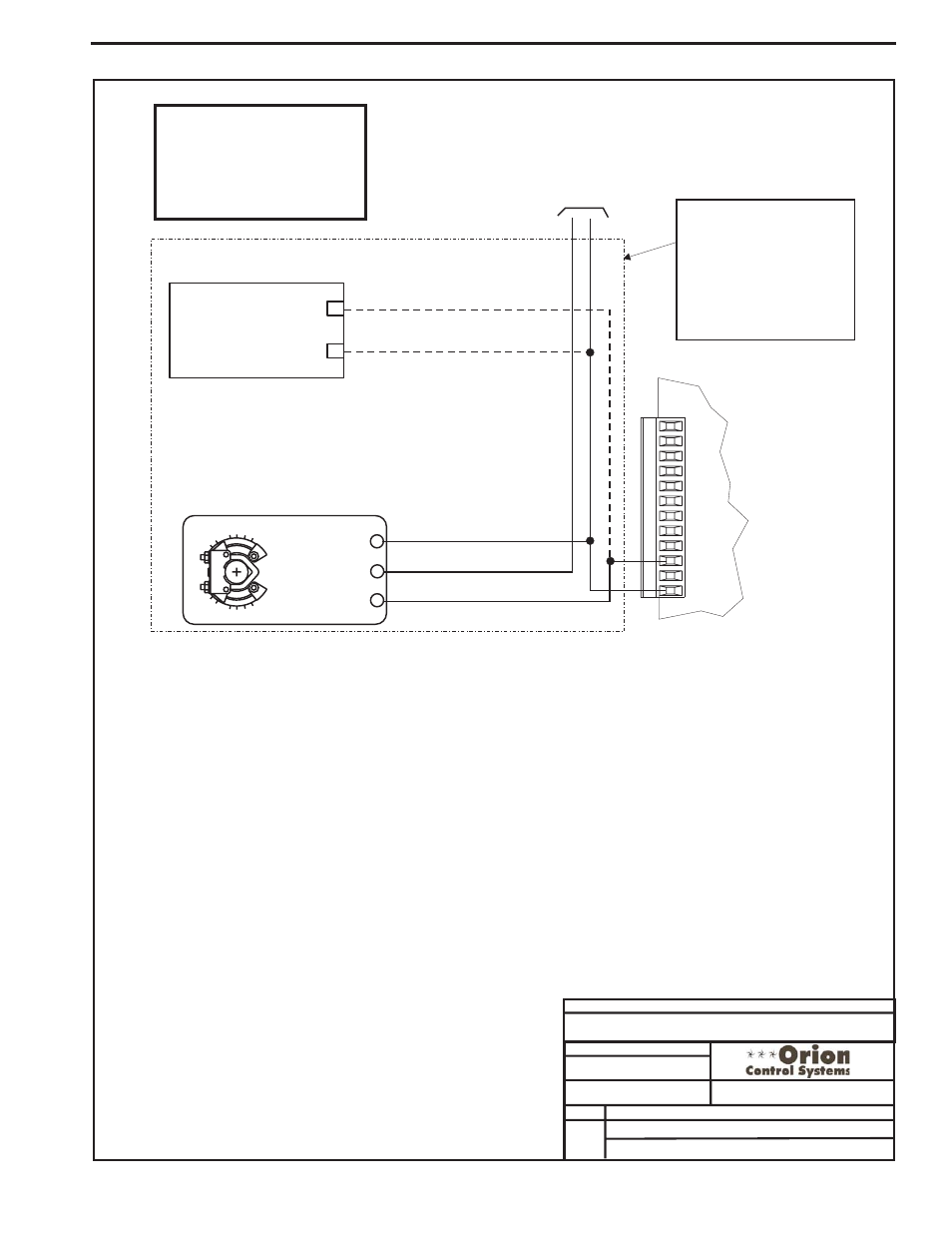
VCM Controller Wiring Detail
Supply Fan VFD or Bypass Damper Actuator
Bypass Damper Actuator
(Belimo Actuator Shown)
0-10 VDC
24 VAC Power Source
Sized For Actuator VA Load
GND
24 VAC
Y1 3
Y1 3
+ 2
+ 2
COM -
1
COM -
1
GND
INPUTS
GND
AOUT1
AOUT2
GND
+VDC
AIN1
AIN2
AIN3
AIN4
AIN5
AIN7
OE331-21-VCM
VCM Controller Board
Belimo Actuator Wiring
Shown. Consult Factory For
Other Manufacturers Wiring
Instructions
+
Supply Fan Variable Frequency Drive
(By Others)
_
VFD 0-10VDC Input
GND
Caution:
The VFD Unit Must Be Configured
For 0-10 VDC Input. The Input
Resistance At The VFD Must Not
Be Less Than 1000 Ohms When
Measured At The VFD Terminals
With All Input Wires Removed.
Note:
Either The Supply Fan
Variable Frequency Drive
Option Or The Bypass
Damper Actuator Option May
Be Connected To AOUT2 On
The VCM Controller. Only
One Option Is Allowed, Not
Both.
Supply Fan VFD & Bypass Damper Actuator Wiring