Gbd controller - co2 apllications wiring, Component & system wiring 75, Gbd device wiring – Orion System VCM Component User Manual
Page 75: Gbd device, 1 of 5, Line voltage 24 vac transformer 20va minimum, Filename date: b. crews description: page drawn by, 24vac, Co sensor wiring, 24 vac pilot duty relay (by others)
Component & System Wiring
75
FILENAME
DATE:
B. CREWS
DESCRIPTION:
PAGE
DRAWN BY:
OE331-21- AVG
JOB NAME
10/07/05
OE331-21-AVG-GBD-Wire1A.CDR
FILENAME
JOB NAME
Note:
All Relay Contacts
Are N.O. & Rated
For 2 Amps
@ 24VAC
Maximum
R1
R2
1 of 5
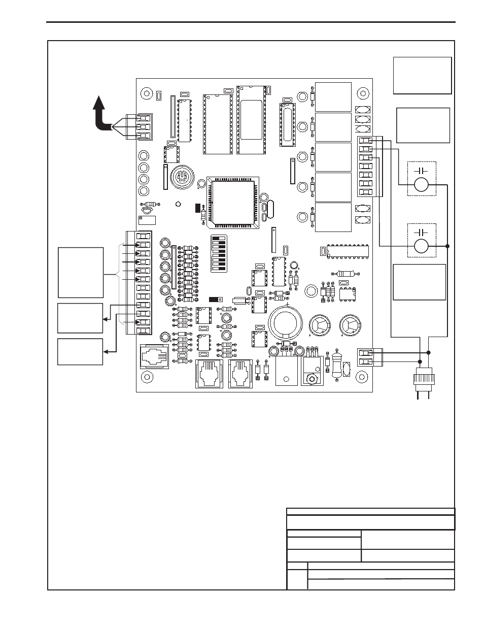
GBD Device Wiring
GBD Device
4.) All Wiring To Be In Accordance
With Local And National Electrical
Codes And Specifications.
3.) Set-up, Programming And
Monitoring Of The GBD Device
Requires The Use Of A Personal
Computer And Prism Software.
4
NETWORK
TOKEN
16
32
8
2
1
24VAC
24VAC
MC34064A
9936
M
T'STAT
1
R
SHLD
T
COMM
1
1
CX10
D7
UL
LABEL
U15
SW1
GND
SENSOR
PRESSURE
TB3
PJ1
PJ2
EXPANSION
C20
R26
CX15
AOUT2
AOUT1
GND
GND
D15
C17
C12
CX13
U13
C10
PU5
PU7
D14
D11
VDC
0-5
PU4
PU3
D8
D9
R10
C18
PJ3
R24
R25
R22
C15
D17
D18
VR1
VR2
D19
C19
R19
C14
JP1
R15
U12
CX14
U14
U10
VDC
0-1
X2
C1
1
CX12
SC1
R13
C13
C7
R7
D12
D10
D13
L1
R27
D16
POWER
V6
TB4
C16
U11
R1
1
C9
R6
RAM
CX2
C1
LED2
VREF ADJ
+VDC
RV1
AIN1
AIN2
AIN3
AIN4
AIN5
AIN7
INPUTS
U7
R1
RN5
C4
PU1
PU2
D6
ADDRESS
TEST POINT
5.11V
+VREF
RN3
EWDOG
R28
CX5
COMM
LED1
PWR
COMM
RS-485
HELD
HAND
U5
C21
TB1
RN1
CX1
U1
U2
V2
CX6
C3
C2
RLY5
RN4
U9
CX9
RLY4
X1
D5
TUC-5R/5R-PLUS
YS101816 REV 4
EPROM
U6
(1 MEG)
RLY3
RN2
D4
RLY2
PAL
D3
COM4-5
V4
K5
U8
V5
TB2
R5
R4
R3
V3
CX3
U3
RLY1
CX4
U4
D2
D1
V1
GND
GND
SERIAL#
CX8
OFF
OE331-21-AVG
GBD Device Wiring
When Used For CO Applications
2
Available Inputs
For Connection
of CO Sensor
4-20mA Signal
See Page 2 For
Detailed
2
CO
Sensor Wiring
2
Connect The GBD To
The Same Local
Communications Loop
As The Controller
That Will Be
Receiving the GBD
Broadcast
Communications Wire
Must Be 2 Conductor
Twisted Pair With
Shield, Belden #82760
Or Equivalent.
All Wiring Must Be
Straight Through,
R To R, T To T And
SHLD To SHLD.
Available Relay #1
24 VAC Output
Closes On Rise
Above Minimum
CO Setpoint
2
24 VAC Pilot Duty
Relay (By Others)
24 VAC Pilot Duty
Relay (By Others)
Available Relay #2
24 VAC Output
Closes On Rise
Above Maximum
CO Setpoint
2
Available
0-10 VDC
Proportional
Output Signal
Available
10 VDC Fixed
Output Signal
R2
R1
COM
1-3
Line Voltage
24 VAC Transformer
20VA Minimum
2.) 24 VAC Must Be Connected
So That All Ground Wires
Remain Common.
Notes:
4.) All Wiring To Be In Accordance
With Local And National Electrical
Codes And Specifications.
3.) Set-up, Programming And
Monitoring Of The GBD Device
Requires The Use Of A Personal
Computer And Prism Software.
1.) The GBD Can Either Be Used
With CO2 Sensors Or Space
Temperature Sensors But Not
Both On The Same GBD Device.
Up to 2 GBD Devices Can Be
Located On Each Local Loop.
GBD Controller - CO2 Apllications Wiring