Modulating heating & cooling wiring, Component & system wiring 48 – Orion System VCM Component User Manual
Page 48
Component & System Wiring
48
FILENAME
DATE:
B. Crews
DESCRIPTION:
PAGE
DRAWN BY:
JOB NAME
OVCM-ModHeat-Cool-Wr1A..CDR
1 of 1
03/06/06
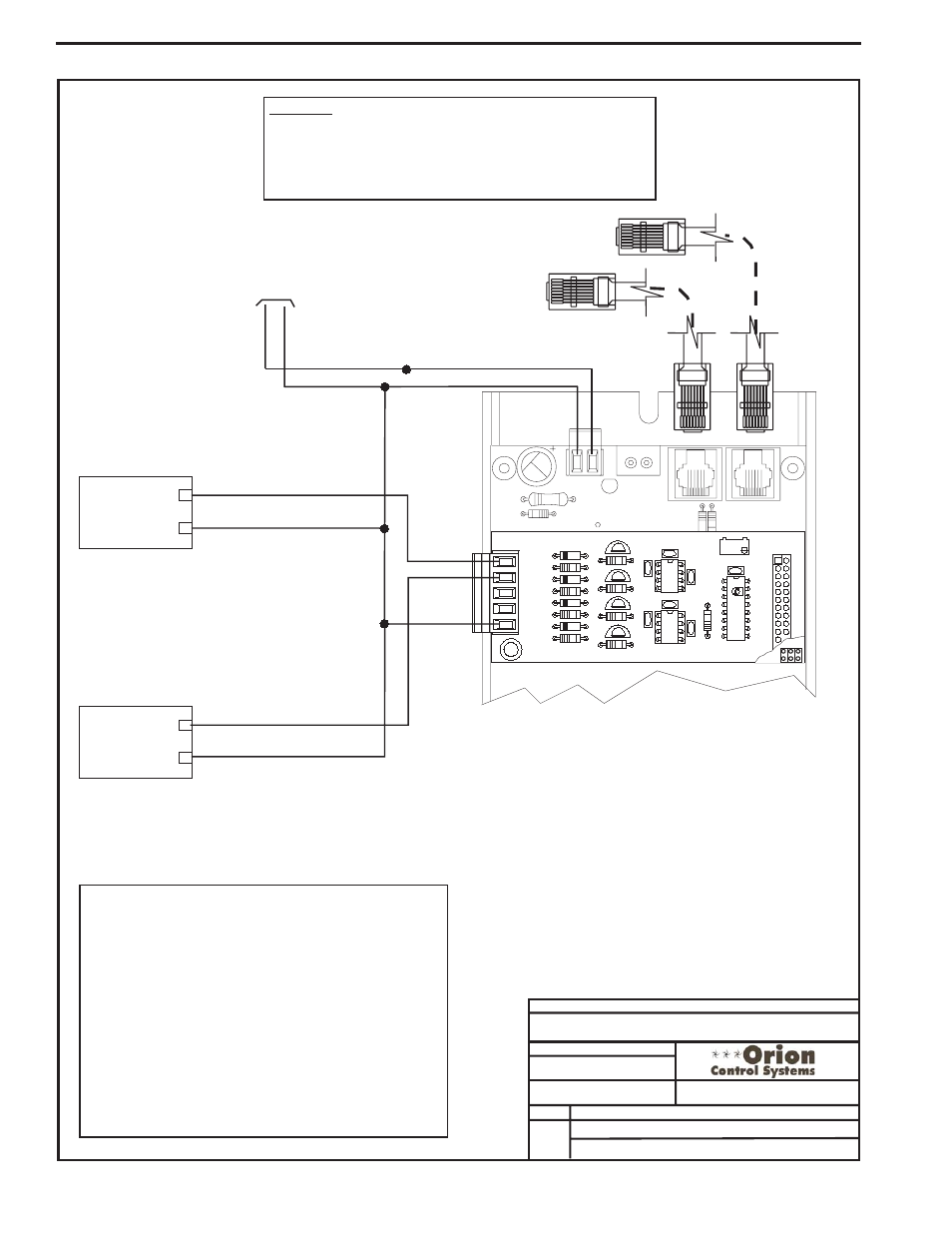
VCM Controller Wiring Detail
Modulating Heating and Cooling
24
V
A
C
GND
10 VA Minimum Power Required For
Each 2 Slot Expansion Base Board.
20 VA Minimum Power Required For
Each 4 Slot Expansion Base Board
R20
C8
TB2
D3
PWR LD1
24V
AC-IN
GND
GND
TB1
PJ2
+24VDC-OUT
R17
PJ1
R15
Connect To VCM Controller
Connect To Next
Expansion Board
(When Used)
GND
AOUT2
AOUT1
OE355
-
4
Analog
Output
Board
OE352 or OE353 Expansion Base Board
WARNING!!
Observe Polarity! All boards must be wired with GND-to-GND and 24VAC-
to-24VAC. Failure to observe polarity will result in damage to one or more
of the boards. Expansion Boards must be wired in such a way that power to
both the expansion boards and the controller are always powered together.
Loss of power to the expansion board will cause the controller to become
inoperative until power is restored to the expansion board.
GND
AOUT1
YS101786
4 AOUT MOD. I/O BD.
CX1
U1
Q1
LM358
R2
U2
R9
D1
R6
D2
R7
D4
D3
R8
TB1
CX2
C3
C1
P1
RV
1
R1
C4
U3
C2
LM358
CX3
AOUT2
AOUT3
AOUT4
Q2
R3
Q4
Q3
R4
R5
+
+
Modulating Heating Device
(By Others)
Modulating Cooling Device
(By Others)
_
_
GND
GND
0-10 VDC or 2-10 VDC
(Configurable)
0-10 VDC, 2-10 VDC or 1.5-5.0 VDC
(Configurable)
The Cooling Device Used Can
Be A Modulating Chilled Water
Valve or A Digital Scroll
Compressor. If Using A Digital
Scroll Compressor Please See
Digital Scroll Detailed Wiring
Information In This Manual.
The Cooling Device Used Can Be A
Modulating Chilled Water Valve or A Digital
Scroll Compressor. If Using A Digital Scroll
Compressor Please See Digital Scroll
Detailed Wiring Information In This Manual.
The Heating Device Used Can Be A
Modulating Hot Water Valve, Modulating
Steam Valve or SCR Controlled Electric
Heating Coil.
Note:
1.)The Modulating Cooling Device Used Must Be Capable Of
Accepting Either A 0-10 VDC, 2-10 VDC Or 1.5-5.0 VDC Input.
The AOUT1
Output Voltage Is User Configurable For These Voltages.
The AOUT2 Output Voltage Is User Configurable For These Voltages
The Modulating Heating Devices Used Must Be Capable Of
Accepting Either A 0-10 VDC Or 2-10 VDC Input.
These
Voltage Outputs Must Be Configured When You are Setting-up The
VCM Controller(s) Operating Parameters. See the VCM Controller
Operator Interfaces Technical Guide For Complete Controller
Programming and Configuration Information.
2.) Each Modulating Heating Or Cooling Device Used On The VCM
Controller Must Have (1) Relay Output Configured For Each Device
Used, In Order To Enable The Modulating Heating And/Or Cooling
Device's Sequence. This Relay Output Must Be Configured When
Setting-up The VCM Controller Operating Parameters. See the VCM
Controller Operator Interfaces Technical Guide For Complete
Controller Programming and Configuration Information.
Modulating Heating & Cooling Wiring