Vav/cav controller setpoints, Vav/cav setpoint screens, Vav/cav/mua operator interface sd 34 – Orion System VAV II Controller v.1 User Manual
Page 34
VAV/CAV CONTROLLER SETPOINTS
VAV/CAV/MUA Operator Interface SD
34
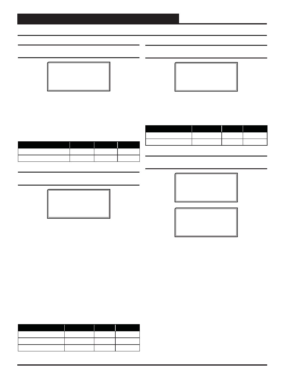
Setpoint Screen #14 - Economizer Minimum
Position & Control Rate
VAV/CAV Spts ID 0001
Economizer Setpoints
Min Position.: 10%
Control Rate.: 90
The Economizer (OA Damper) Min Position Setpoint is maintained
during the Occupied Mode even if the Economizer is disabled due to the
OA Temperature or Wetbulb Temperature being above the Economizer
Enable Setpoint. The Control Rate Setpoint allows you to adjust the
Economizer to modulate the OA Damper Actuator faster or slower as
desired. The Control Rate Setpoint range is 10-99. Larger numbers make
the Economizer Outdoor Air Damper Actuator modulate faster; smaller
numbers make the Outdoor Air Damper Actuator modulate slower.
Description
Minimum
Default
Maximum
Economizer Min Position
0%
10%
100%
Economizer Control Rate
10
90
99
Setpoint Screen #15 - Static Setpoint,
Deadband & Control Rate
VAV/CAV Spts ID 0001
Static Spt...: 0.50”
Deadband.....: 0.10”
Control Rate.: 10s
For VAV units, a Supply Fan VFD or Bypass Damper Actuator is used to
maintain the Duct Static Pressure Setpoint. The Static Pressure Output
Signal varies to control the Static Pressure Setpoint. If the Duct Static
Pressure is above the Static Setpoint plus the Deadband, the Static Pres-
sure Output Signal will be reduced at every Control Rate interval. If the
Static Pressure is below the Static Setpoint minus the Deadband, the
Output signal will be increased at every Control Rate interval.
The Duct Static Pressure Control Output Signal is a non-confi gurable
Direct Acting Signal (0-10 VDC). This can be used to directly connect
to a Supply Fan VFD without any modifi cations.
When you are using a Bypass Damper Actuator to control the Duct
Static Pressure, you must set up the Bypass Damper Actuator or the
Bypass Damper so that it is Reverse Acting in operation. The Output
Signal increases (closes Bypass Damper) if the Duct Static Pressure is
below the Duct Static Pressure Setpoint by the Deadband amount and
the Output Signal decreases (opens Bypass Damper) if the Static Pres-
sure is above the Setpoint by the Deadband amount.
Description
Minimum
Default
Maximum
Static Spt
0.10″ WG
0.50″ WG
3.0″ WG
Deadband
0.01″ WG
0.10″ WG
1.0″ WG
Control Rate
1 Sec
10 Sec
30 Sec
VAV/CAV Setpoint Screens
Setpoint Screen #16 - Building Pressure
Setpoint & Deadband
VAV/CAV Spts ID 0001
Relief Spt..: 0.10”
Deadband....: 0.02”
The VAV/CAV Controller uses the Relief Fan VFD signal to maintain
the Relief Setpoint value plus or minus the Deadband value. Adjustments
to the signal are made at a rate equal to the Control Rate Setpoint on
the previous Static Pressure screen. If you don’t require Relief Pressure
control, simply ignore these settings
Description
Min.
Default
Max.
Relief Setpoint
-0.20″ WG
0.10″ WG
+0.20″ WG
Deadband
0.01″ WG
0.02″ WG
0.10″ WG
Setpoint Screens #17 & 18 - SAT Cool Reset &
SAT High Reset
VAV/CAV Spts ID 0001
Set SAT Cool Reset
Hi Rst = 0 Spt = 55
Lo Rst = 0 Ofst = 0
VAV/CAV Spts ID 0001
Set SAT Heat Reset
Hi Rst = 0 Spt = 140
Lo Rst = 0 Rst = 140
These screens allow you to set values for resetting the Supply Air
Temperature (SAT) when the unit is in Cooling and/or Heating Mode.
You can confi gure the HVAC unit to reset the SAT Setpoint based on
the Outdoor Air Temperature, Input Voltage Signal, Space Temperature,
Return Air Temperature, Fan VFD Percentage, or a Local Analog Value.
On these screens you will only enter the values in the left hand column.
These are the Reset Source values that will cause the SAT to proportion-
ally reset from its minimum to its maximum value. The values in the
right hand column are set in Setpoint Screens #4 & #5 on page 32 and
automatically imported into this screen. See the examples below to set
up the reset ranges.
Example: Space Temperature Setpoints are 74°F COOL and 72°F HEAT
Space Temperature Cool Reset Example:
Hi Reset = 76°F
SAT Setpoint (Spt) = 55°F
Lo Reset = 74°F
SAT Setpoint (Rst) = 65°F
Space Temperature Heat Reset Example:
Hi Reset = 72°F
SAT Setpoint (Spt) = 90°F
Lo Reset = 70°F
SAT Setpoint (Rst) = 120°F
- CAV II Controller v.1 MUA II Controller v.1 VAV II Controller v.2 CAV II Controller v.2 MUA II Controller v.2 Modular System Manager SD VCB-X VCB-X Controller VCC-X Controller VCB-X Modular Service Tool VCM Controller Operator Interfaces SD VCM-X/RNE Controller VCC-X VCM-X/RNE Controller Operator Interface SD SA E-BUS Controller Modular System Manager SD Quick Start