Vav/cav controller setpoints, Vav/cav setpoint screens, Vav/cav/mua operator interface sd 32 – Orion System VAV II Controller v.1 User Manual
Page 32
VAV/CAV CONTROLLER SETPOINTS
VAV/CAV/MUA Operator Interface SD
32
Description
Minimum
Default
Maximum
SAT Heating Spt
60ºF
140ºF
200ºF
Reset Limit Spt
60ºF
140ºF
200ºF
Setpoint Screen #6 - Heating/Cooling Supply
Control Use Deadband Of
VAV/CAV Spts ID 0001
Both Heating/Cooling
Supply Control Use
Deadband Of: 1ºF
All Heating and Cooling stages are staged up and down as the Supply
Air rises above or falls below the Supply Setpoint by an amount equal
to the number of stages divided into the Deadband Setpoint.
If you have 2 stages and a 1°F deadband, the staging begins at 0.5°F
above the setpoint for Stage 1 and 1°F above the setpoint for Stage 2.
Description
Minimum
Default
Maximum
Deadband Setpoint
0ºF
1ºF
20ºF
Setpoint Screen #7 - Morning Warm Up Setup
VAV/CAV Spts ID 0001
Morning WarmUp Setup
Target Temp: 72º F
Max Length.: 60 Min
If you need a Morning Warm-Up period on your HVAC unit, enter the
Target Temperature you want the Return Air Temperature to achieve and
the Max Length of time you want to spend in Warm-Up Mode trying to
achieve the Target Temperature. If you don’t need Morning Warm-Up,
simply ignore the Target Temperature Setpoint and enter a ‘0’ for the
Max Length value.
Description
Minimum
Default
Maximum
Target Temperature
50ºF
72ºF
90ºF
Max Length
0 Min
60 Min
240 Min
Setpoint Screen #8 - Outdoor Air Lockouts
VAV/CAV Spts ID 0001
Outdoor Air Lockouts
Cooling......: 50ºF
Heating......: 75ºF
The Unit Controller will Lockout Mechanical Heating or Cooling when
the Outdoor Air (OA) Temperature is above or below these setpoints.
On Heat Pump units, Compressor Cooling and Heating can only oper-
ate if the OA Temperature is above the Outdoor Air Cooling Lockouts.
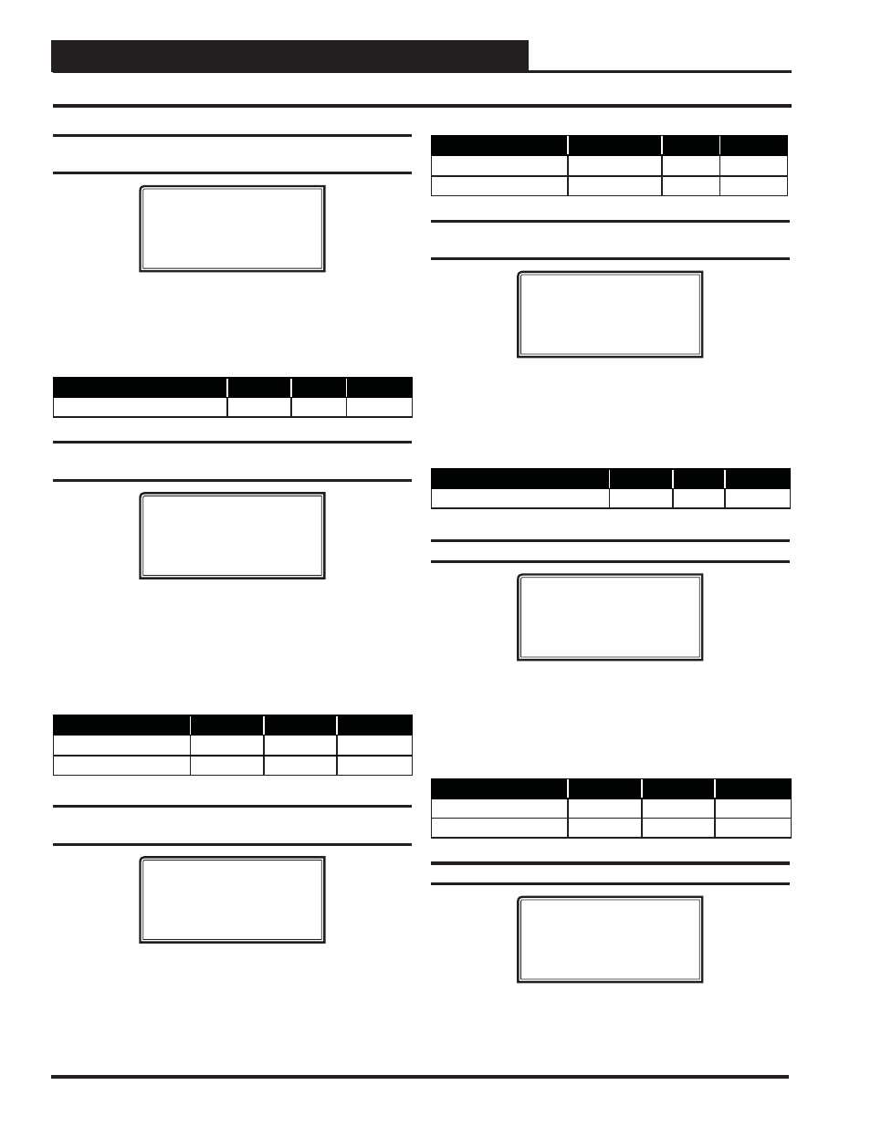
Setpoint Screen #3 - HVAC Mode Select
Deadband
VAV/CAV Spts ID 0001
HVAC Mode Select
Deadband....: 1.0ºF
The HVAC Mode Select Deadband is the amount of error from setpoint
required to activate the Heating or Cooling Mode of operation.
This assumes the Return Air or Space Temperature are the controlling
sensors. If the Supply Air Temperature Sensor is the controlling sensor,
then this setpoint is not used.
Description
Minimum
Default
Maximum
HVAC Mode Select Deadband
0.1ºF
1.0ºF
10.0ºF
Setpoint Screen #4 - SAT Cooling Setpoint &
Reset Offset
VAV/CAV Spts ID 0001
Supply Air Setpoints
Cooling......: 55ºF
Reset Offset...: 0ºF
If no Reset of the Supply Air Temperature (SAT) Setpoint will be used,
then set the Cooling SAT Setpoint here, and leave the Reset Offset at 0.
If SAT Reset will be used, enter a Reset Offset value that will be added
to the Cooling Setpoint to create the upper limit for the Reset function.
Reset is always upward from the SAT Cooling Setpoint (lowest value) to
the SAT Cooling Setpoint plus Offset (highest value). This Cooling Reset
confi guration will be completed on Setpoint Screen #17 on page 34.
Description
Minimum
Default
Maximum
SAT Cooling Setpoint
40ºF
55ºF
70ºF
Cooling Reset Offset
0ºF
0ºF
20ºF
Setpoint Screen #5 - SAT Heating & Reset
Limit Setpoints
VAV/CAV Spts ID 0001
Supply Air Setpoints
Heating......: 140ºF
Reset Limit...: 140ºF
If no Reset of the Supply Air Temperature (SAT) Setpoint will be used,
then set the Heating SAT Setpoint here, and set the Reset Limit to the
same value. If SAT Reset will be used, set the Heating Setpoint as the
lowest Supply Air Setpoint Temperature desired, and set the Reset Limit
as the highest SAT desired. Reset is always upward from the Heating
Setpoint to the Reset Limit. This Heating Reset confi guration will be
completed on Setpoint Screen #18 on page 34.
VAV/CAV Setpoint Screens
- CAV II Controller v.1 MUA II Controller v.1 VAV II Controller v.2 CAV II Controller v.2 MUA II Controller v.2 Modular System Manager SD VCB-X VCB-X Controller VCC-X Controller VCB-X Modular Service Tool VCM Controller Operator Interfaces SD VCM-X/RNE Controller VCC-X VCM-X/RNE Controller Operator Interface SD SA E-BUS Controller Modular System Manager SD Quick Start