Vav/cav controller configuration, Vav/cav confi guration screens, Vav/cav/mua operator interface sd – Orion System VAV II Controller v.1 User Manual
Page 27
VAV/CAV/MUA Operator Interface SD
VAV/CAV CONTROLLER CONFIGURATION
27
VAV/CAV Confi guration Screens
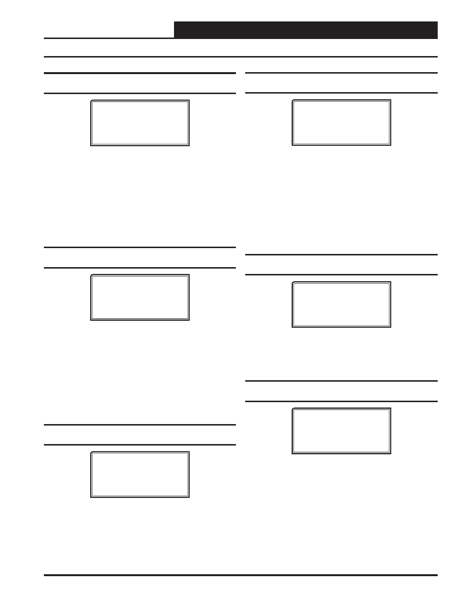
Confi guration Screen #10 - Supply Air
Setpoint Reset Source
VAV/CAV Cnfg ID 0001
Reset SAT Stpt Using
Input Voltage Signal
Use < Or > To Change
Select the desired method of resetting the Heating/Cooling Supply Air
Setpoint. Default is Input Voltage Signal. Available selections are:
• Input
Voltage
Signal
• Outdoor
Air
Sensor
• Space
Sensor
• Fan
VFD
Percentage
• Local
Analog
Value
• Return
Temp
Sensor
Confi guration Screen #11 - Type of
CO
2
Sensor Installed
VAV/CAV Cnfg ID 0001
CO2 Sensor Installed
Sensor Type: NONE
Use < Or > To Change
You can install a CO
2
Sensor on this HVAC unit to monitor the Carbon
Dioxide levels and/or to provide for Indoor Air Quality (IAQ) con-
trol. If you only want to monitor the level, enter the same Maximum
Economizer Position that you set for the Minimum Position and it will
not be reset as the CO
2
level increases. If you do want IAQ control, set
the desired Maximum Economizer Position to reset up to during high
levels of CO
2
. The VAV/CAV Controller needs to know what type of
CO
2
Sensor signal output is being provided. Select either VDC (0-10)
or mA (4-20) as the CO
2
Sensor signal. Select NONE if no CO
2
sensor
is used. Default is NONE.
Confi guration Screen #12 - CO2 Sensor
Maximum Reading
VAV/CAV Cnfg ID 0001
CO2 Sensor Maximum
Reading: 2000ppm
Enter 0 If No Sensor
The VAV/CAV Controller needs to know the CO
2
Sensor scaling for
proper reading of the CO
2
Sensor output. The Standard CO
2
Sensor
should be scaled to 2000 PPM. Enter
<0>
if no CO
2
Sensor is being
used. Default is 2000ppm.
Confi guration Screen #13 - Air to Air Heat
Pump Control
VAV/CAV Cnfg ID 0001
Air to Air Heat Pump
Control: No
Use < Or > To Change
The VAV/CAV Controller can be confi gured to operate as an Air To Air
Heat Pump Controller. If you make this selection, the same relays are
used to stage the compressors in both the Heating and Cooling Modes.
The only difference is that a separate Reversing Valve relay will activate
in the Heating Mode to enable Heating to occur. You must confi gure at
least one relay for the reversing valve.
You can also confi gure for an Auxiliary Heat relay that will activate
whenever the Supply Air drops below the Supply Setpoint by 5°F to
provide Heat when the Outdoor Air is too cold for the Heating Mode to
operate correctly. Default is No.
Confi guration Screen #14 - Broadcast Time
Clock to All Loop Units
VAV/CAV Cnfg ID 0001
Broadcast Time Clock
To Loop Units: No
Use < Or > To Change
This setting enables the VAV/CAV Controller to send its real time clock
information to all controllers on the local loop. This must be used when
connecting VAV/Zone Controllers on the local loop, but can be used to
synchronize clock time in all controllers on the local loop.
Confi guration Screen #15 - Broadcast Outdoor
Temperature
VAV/CAV Cnfg ID 0001
Broadcast Outside
Temperature: No
Use < Or > To Change
This setting enables the VAV/CAV Controller to send its Outdoor Air
Temperature reading to all other controllers on the entire system. It is
specifi cally used when more than one HVAC unit is installed and only
one Outdoor Air Sensor is used to supply its signal to all controllers.
Default is No.
- CAV II Controller v.1 MUA II Controller v.1 VAV II Controller v.2 CAV II Controller v.2 MUA II Controller v.2 Modular System Manager SD VCB-X VCB-X Controller VCC-X Controller VCB-X Modular Service Tool VCM Controller Operator Interfaces SD VCM-X/RNE Controller VCC-X VCM-X/RNE Controller Operator Interface SD SA E-BUS Controller Modular System Manager SD Quick Start