Measurement Computing CIO-EXP-GP User Manual
Page 9
3.5 Powering The CIO-EXP-GP
The CIO-EXP-GP can be powered through the 37-pin cable, the power screw terminal or the Molex
connector. The power that can be carried through the 37-pin connector is limited so we recommend
using this source only when a single CIO-EXP-GP is used.
The power required to run a CIO-EXP-GP is dependent on the board configuration. Remember that
additional power will be drawn when the CIO-EXP-GP is configured for resistance measurement (bridge
configuration) due to the current required for each bridge.
3.5.1
Power Source Switch
10V
+5 CO
MP
X2
.5
GN
D
0.
5V
1V
2V
4V
S17
RE
M
X1
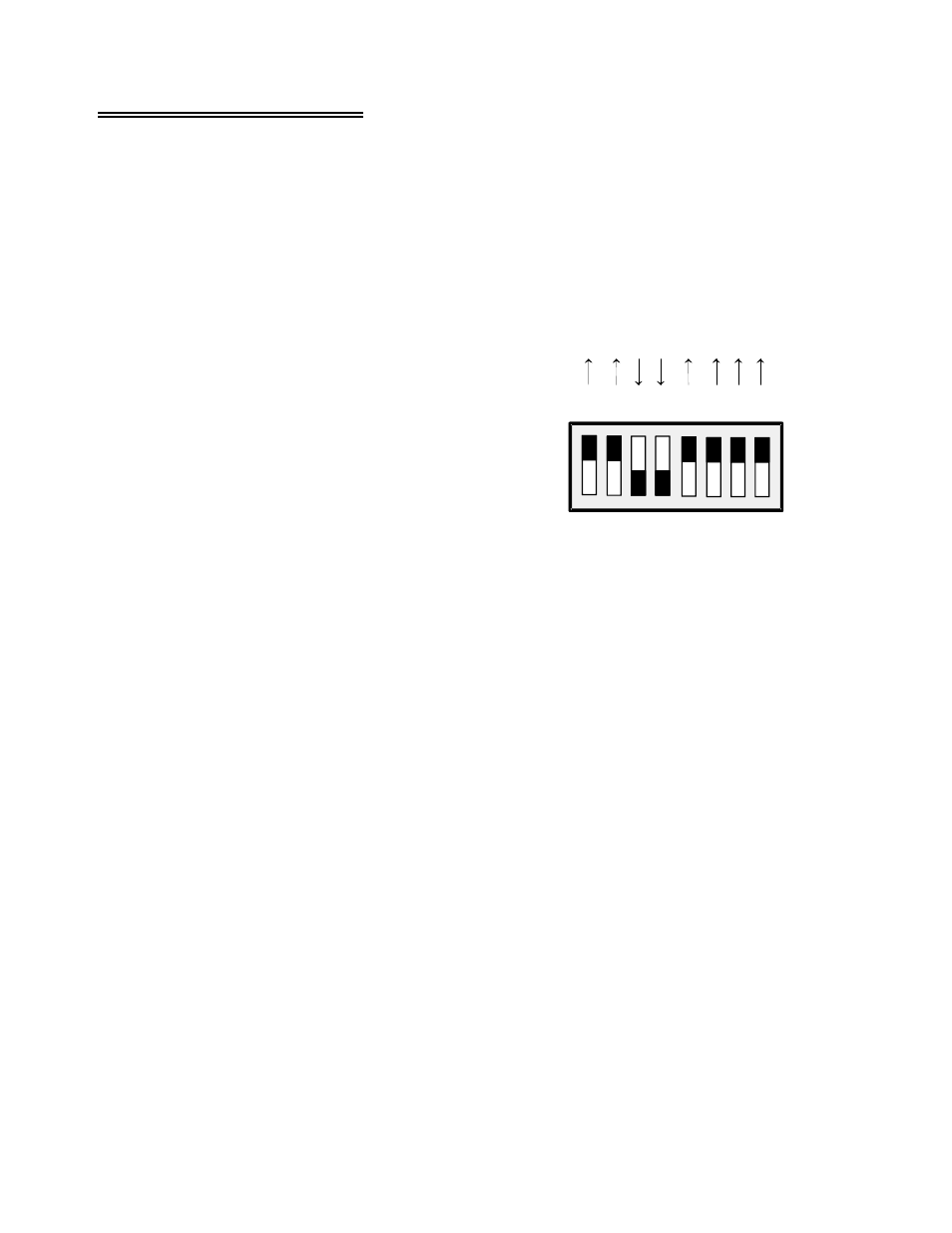
One of the switches on the eight-position DIP switch (S17) near
the output channel jumpers controls the source of the +5 volts
power to the board. Shown in Figure 3-5 it is the 3rd switch
from the left.
When positioned down, (ON, +5 COMP), the +5V power is
drawn from the personal computer through the signal cable.
When positioned up (OFF, REM) , +5V power is taken from
the optional external 5V power connector (the Molex connector
labeled P19) or the +5V screw terminal connection.
Figure 3-5. Power Source Switch
3.5.2
Powering with the 37-Pin Connector
You can power the CIO-EXP-GP via the 37-pin cable. No more than one CIO-EXP-GP should be
powered using the 37-pin cable.
This option is not available when using some A/D boards. If the A/D board you are using supplies +5V
at pin 29 (or at pin 1 when using the C-EXP2DAS16 signal cable), you can power the CIO-EXP-GP
through the 37 pin connector by setting the power select switch on S17 to “+5 COMP”.
3.5.3
Powering with the Molex Connector
The CIO-EXP-GP can be powered off the PC's power supply by connecting the optional external 5V
power connector (the Molex connector labeled P19) to the PC’s power supply through a C-MOLEX-10
cable. This cable has the same Molex connector that is used inside the PC and so can be connected
directly to the PC's power supply through one of the spare connectors. The cable is keyed, so it should
not be forced. When inserted properly it will slide easily and snap in place.
3.5.4
Powering Through the Power Screw Terminals:
A set of screw terminals labeled “+5V REM” and “REM GND” are located below the 37-pin connectors
P1 and P2. You can power the CIO-EXP-GP from a +5V (±5%) power supply capable of at least 400
mA. For this option, set the power select switch on S17 to “REM”.
CAUTION: Connect the ground of the power supply to the ground of the personal computer with a
heavy gauge wire. If you do not strap the two grounds together, a voltage between these grounds will
5