Ch4 in config, 3 input configuration, 1 setting the input configuration – Measurement Computing CIO-EXP-GP User Manual
Page 19: 2 enabling open thermocouple detection (otd)
1 2 3 4 5 6 7
8 9 10 11 12
14 15
0
13
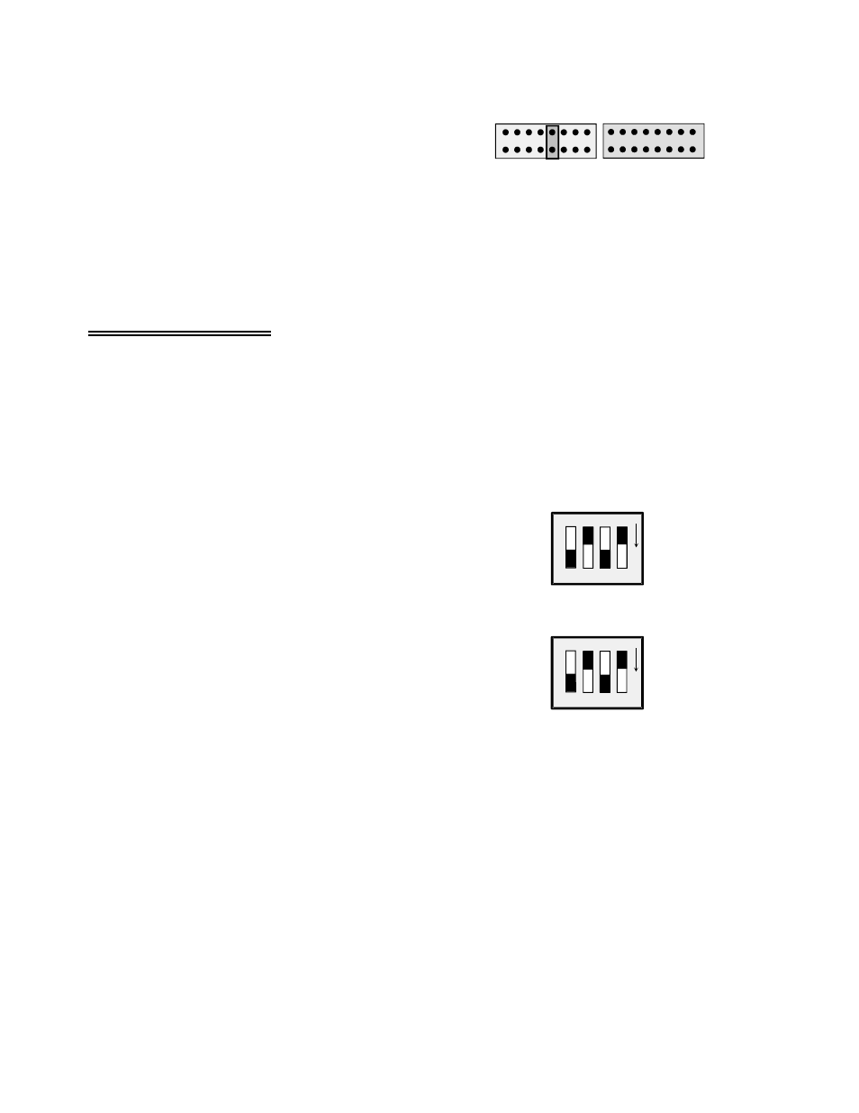
CJC SEL
CHANNEL 4 SELECTED
FOR COLD JUNCTION SENSOR OUTPUT
The jumper for the CJC channel select (Figure 5-1)
looks just like the jumper for output channel
selection.
Set this jumper according to the instructions for the
software package you are using.
Figure 5-1. CJC Channel Select Jumper Pad
The CJC uses one analog input channel of the A/D board. The channel selected must be unique (the CJC
SEL jumper must not be set to the same number as that for CH SEL jumper or VEXC SEL jumper on this
board or any other EXP board that may be daisy-chained to this board).
5.3 Input Configuration
For thermocouple measurement, the channel input configuration switches must be set for two wire
measurement. Also, a ground reference should be established and open thermocouple detection should
be enabled. These options are selected by setting some switches and closing some solder pads on the
underside of the CIO-EXP-GP.
5.3.1
Setting the Input Configuration
3
4
3
4
CH0
O
N
O
N
CH4
IN CONFIG
3
4
3
4
CHANNEL CONFIGURATION SWITCH SET FOR THERMOCOUPLES
BOTH 4s ARE ON (DOWN), BOTH 3s ARE OFF (UP)
A channel configuration switch is associated with each
channel. The switch is used to configure the input circuit
for two or four wire measurements. When measuring
thermocouples, two wire measurement should be used.
Set the two switches labeled “4” on each IN CONFIG
Channel Configuration switch to the ON (down) position for
each channel used for thermocouple measurement. (See
Figure 5-2 on the right.)
Set the two switches labeled “3” on each IN CONFIG switch
for thermocouple channels to the OFF (up) position.
Figure 5-2. Channel Configuration Switches
5.3.2
Enabling Open Thermocouple Detection (OTD)
Open thermocouple detection (OTD) is enabled for a channel by installing a resistor and closing the 'TC'
pad with a solder bridge (see Figures 5-3 and 5-4). There are locations marked “TC” for each channel for
this purpose.
OTD provides the high side of the thermocouple signal with a reference to
−
50mVDC at very low
current. If a thermocouple opens, it ceases to produce a voltage. If that happens, the OTD voltage drives
the signal on that channel to full minus. Most software is set up to alarm for an open thermocouple when
a temperature falls to full scale minus value. The CIO-EXP-GP will accurately measure thermocouples
without the 'TC' pad closed but you must close it and install a 100K resistor to have OTD.
15