Measurement Computing CIO-EXP-GP User Manual
Page 23
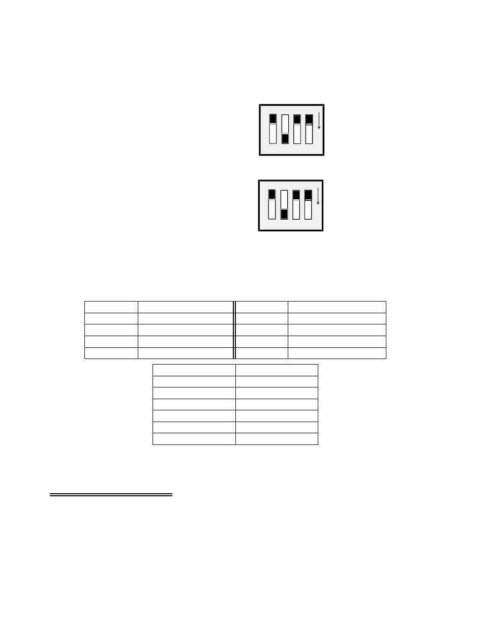
There is a gain switch for each channel (Figure 5-6). Set the input channel gain to match the expected
voltage output of the bridge you are measuring to the input range of the A/D board as described above.
CH0
X10
00
X10
0
X10
U
GAIN FOR CHANNELS 0 and 4
SET FOR A GAIN OF 10.
SLIDER DOWN SELECTS GAIN
ALL OTHERS TO BE OFF (UP)
O
N
O
N
CH4
Channel Gain Switches
There is a set of DIP gain switches for each input
circuit labeled GAIN (Figure 5-6). There are four,
two-position switches for each channel. The gain
switches are labeled U, X10, X100, and X1000.
Select a gain (higher than unity) by moving the
switch for that gain down. All other switches should
be left in the UP position.
A custom gain may be selected on the CIO-EXP-GP
by installing a precision resistor and setting the
switch marked “U” (User) in the down position. See
Table 5-2 below for positions and some sample gain
values.
Figure 5-6. Channel Gain Switches
Table 5-2. User Gain Resistors - Identities
RX107
7
RX103
3
RX106
6
RX102
2
RX105
5
RX101
1
RX104
4
RX100
0
Resistor Position
Channel
Resistor Position
Channel
10 Ohms
800
17 Ohms
700
40 Ohms
500
161 Ohms
200
364 Ohms
100
776 Ohms
50
Resistor Value
Gain
The equation for selecting the gain resistor is:
R
USER
= (40000 / (Gain
−
1) )
−
40
5.6 Verifying the Installation
Your channel is now configured to make thermocouple measurements. To verify the installation, use the
InstaCal program installed on your computer. This software came with your A/D board if you bought the
board from the same manufacturer as the CIO-EXP-GP. Use the CALIBRATE option to calibrate the
CJC and verify the operation of the channel. Use the TEST option to make a measurement in
engineering units.
19