Measurement Computing CIO-EXP-GP User Manual
Page 27
6.6.2
Setting the Channel Gain
CH0
X1
0
0
0
X1
0
0
X1
0
U
GAIN FOR CHANNELS 0 and 4
SET FOR A GAIN OF 10.
SLIDER DOWN SELECTS GAIN
ALL OTHERS TO BE OFF (UP)
O
N
O
N
CH4
Channel Gain Switches
There is a set of gain switches for each input circuit
(Figure 6-2). There are two, 4-switch DIP blocks for
each channel. One is labeled “GAIN” and the other “IN
CONFIG”. The gain switches are labeled U (user), 10,
100, and 1000.
Set the gain of your choice by placing a slide switch into
the ON (down) position.
The “U” switch and associated user resistor is of no
value to RTD measurement since the minimum specified
value produces a gain of X100, for which there is a
switch. A gain of X100 is the maximum you would use
with an RTD.
Figure 6-2. Channel Gain Switches
6.7 Input Configuration
RTDs may have 2, 3 or 4 wires coming from the probe. A switch labeled “IN CONFIG” must be set to
match the number of wires on your RTD. There is one switch per channel.
RTD Type
IN CONFIG Setting
2 Wire
4 & 4 ON, 3 & 3 OFF
3 Wire
3 & 3 ON, 4 & 4 OFF
4 Wire
4 & 4 ON, 3 & 3 OFF
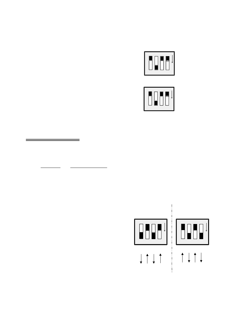
6.7.1
Setting the Input Configuration
CH0
O
N
IN CONFIG
3
4
3
4
SET FOR 2- AND 4-WIRE RTDs SET FOR 3-WIRE RTDs
CH0
O
N
IN CONFIG
3
4
3
4
A channel configuration switch is associated with
each channel. The switch is used to configure the
input circuit for 2, 3, or 4-wire RTDs (Figure 6-2).
Two- and four-wire RTDs share the same switch
position. Set both “4” switches ON (down) and
both “3” switches OFF (up).
For three-wire RTDs, set both “3” switches ON
(down) and both “4” switches OFF (up).
Figure 6-2. Channel Configuration Switches - RTDs
23