Ch4 in config – Measurement Computing CIO-EXP-GP User Manual
Page 34
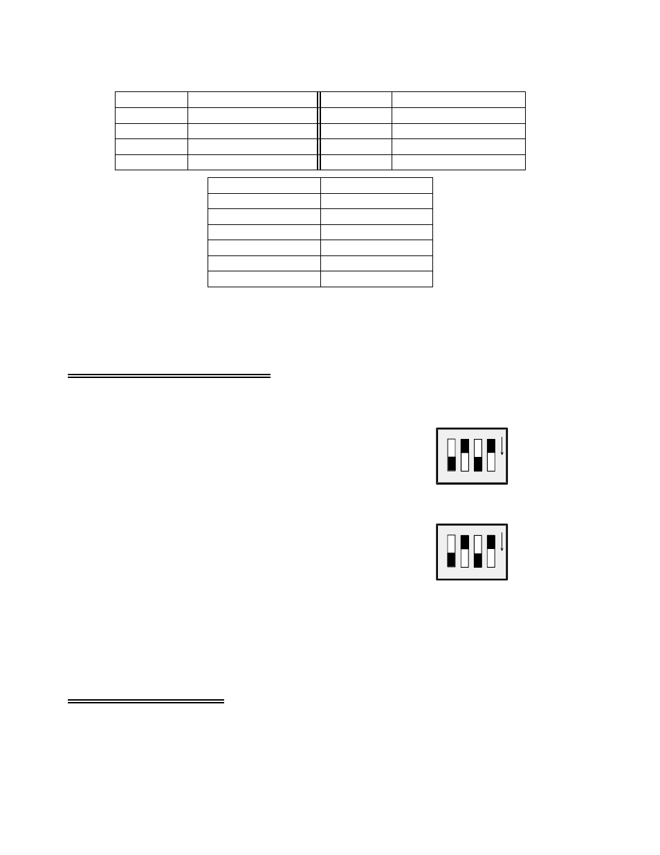
Table 7-1. User-Specified Gain Resistor Positions
RX107
7
RX103
3
RX106
6
RX102
2
RX105
5
RX101
1
RX104
4
RX100
0
Resistor Position
Channel
Resistor Position
Channel
10 Ohms
800
17 Ohms
700
40 Ohms
500
130 Ohms
300
161 Ohms
200
364 Ohms
100
Resistor Value
Gain
The equation for selecting the gain resistor, R
USER,
for any gain between X100 and X1000 is:
R
USER
= (40000 / (Gain
−
1) )
−
40
7.7 Setting the Input Configuration
CHANNEL CONFIGURATION SWITCHES SET
VOLTAGE, THERMOCOUPLES, OR 2/4-WIRE RTDs
BOTH 4s ARE ON (DOWN), BOTH 3s ARE OFF (UP)
3
4
3
4
CH0
O
N
O
N
CH4
IN CONFIG
3
4
3
4
Channel Configuration Switch - Voltages
A channel configuration switch is associated with each
channel (Figure 7-5). The switches are used to configure the
input circuits for voltage inputs, thermocouple inputs, 2, 3, or
4-wire RTDs and bridges.
For bridge measurements on a particular channel, set the
switches labeled “4” to the ON (down) position for that
channel.
Set the switches labeled “3” in the OFF (up) position.
Figure 7-5.
Input Channel Configuration Switches
7.8 Configuring the Bridge
As mentioned earlier in this chapter, resistance measurements are made by constructing a bridge
containing precision resistors with known values against which the unknown resistor is to be compared.
In strain gauge applications, the strain gauge sensor itself may make up a quarter of this bridge, half of
30