Measurement Computing CIO-EXP-GP User Manual
Page 33
7.6.1
Setting the Board Gain
10
V
+5
CO
M
P
X2
.5
GND
0.
5V
1V
2V
4V
S17
RE
M
X1
There is a switch on DIP switch block S17
(Figure 7-3) labeled X1 and X2.5. Sliding this
switch down amplifies the output of the
multiplexers by 2.5. The factory default
position (up) has a gain of 1 (unity).
The X2.5 gain switch is useful in some voltage
and bridge measurements. If you desire a
voltage gain of 2.5, 25, 250 or 2500, set this
switch down.
Figure 7-3. Board Gain
The effect of this switch is multiplicative with respect to the individual channel gains. For example, if
you have set an input channel gain to X100 and the board output gain to X2.5, the signal is amplified by
250 before it reaches the A/D board.
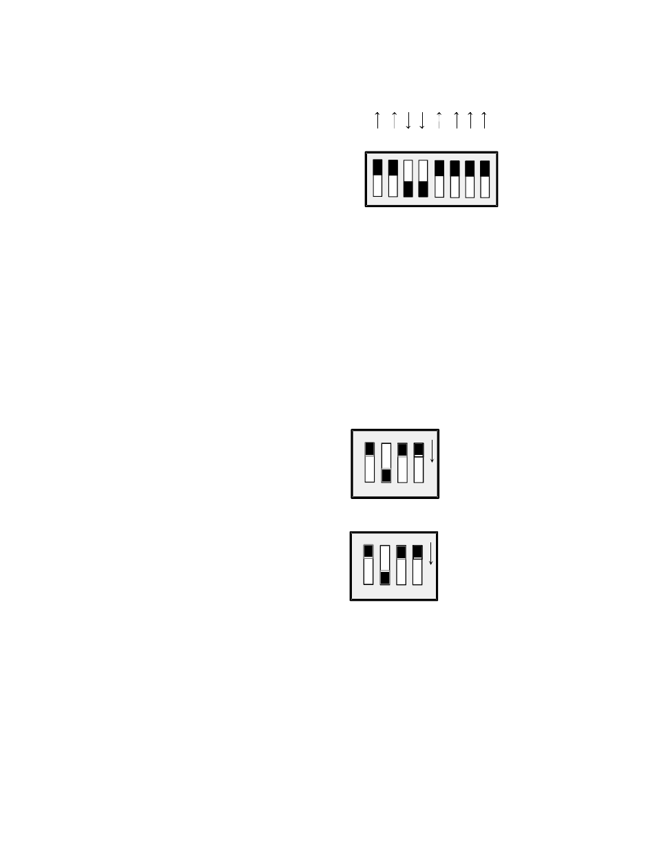
7.6.2
Setting the Channel Gain
There is a gain switch for each channel (Figure 7-4). Set the input channel gain to match the expected
voltage output of the bridge you are measuring to the input range of the A/D board as described above.
CH0
X10
00
X10
0
X10
U
GAIN FOR CHANNELS 0 and 4
SET FOR A GAIN OF 10.
SLIDER DOWN SELECTS GAIN
ALL OTHERS TO BE OFF (UP)
O
N
O
N
CH4
Channel Gain Switches
There is a set of DIP gain switches for each input
circuit labeled GAIN (Figure 7-4). There are four,
two-position switches for each channel. The gain
switches are labeled U, X10, X100, and X1000.
Select a gain (higher than unity) by moving the
switch for that gain down. All other switches should
be left in the UP position.
A custom gain may be selected on the CIO-EXP-GP
by installing a precision resistor and setting the
switch marked “U” (User) in the down position. See
Table 7-1 below for positions and some sample gain
values.
Figure 7-4. Input Channel Gain Switches
29