3general configuration, 1 a/d board type select jumper, 2 setting the output channel – Measurement Computing CIO-EXP-GP User Manual
Page 6: Figure 3-2. output channel select jumper 2
3
GENERAL CONFIGURATION
3.1 A/D Board Type Select Jumper
The CIO-EXP-GP can be used with either DAS08 or DAS16 family boards because the signal
assignments of the 37-pin connectors match those of the DAS08 and may be adapted to those of the
DAS16 with a C-EXP2DAS16-10 cable. Select the A/D board type via the JB10 jumper.
'$6 '$6
Jumper JB10 on the ,CIO-EXP-GP located near the 37-pin connector, selects the
A/D board family as DAS08 or DAS16.
Figure 3-1 shows the jumper set to use the CIO-EXP-GP with a CIO-DAS08
family board.
Figure 3-1
DAS Family Select
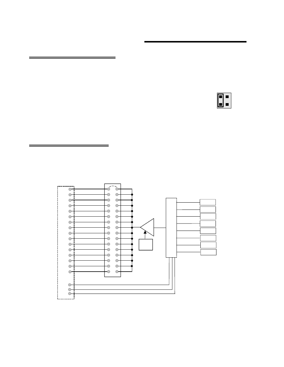
3.2 Setting The Output Channel
Jumpers labeled “CH SEL” located near the 37-pin connector select the A/D board channel that the
output from the active sensor will be connected to.
1
2
3
4
5
6
7
8
9
10
11
12
14
15
0
13
36
35
34
33
32
31
30
18
17
16
15
14
12
11
37-Pin
CONNECTORS
37
13
OUTPUT CHANNEL
SELECT JUMPER
AMP
GAIN
1 OR 2.5
MUX ADDR 1
9
8
7
MUX ADDR 2
MUX ADDR 3
INPUT 0
INPUT 1
INPUT 2
INPUT 3
INPUT 4
INPUT 5
INPUT 6
INPUT 7
8-C
H
A
N
N
E
L
M
U
L
T
IP
LE
XE
R
P1 & P2
Figure 3-2. Output Channel Select Jumper
2