Ab c d arm null pot – Measurement Computing CIO-EXP-GP User Manual
Page 39
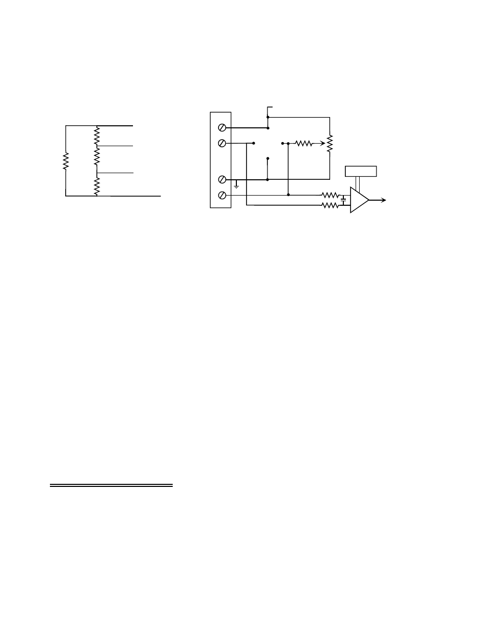
Full Bridge Example
Full bridge strain gauges consist of all four bridge resistors (Figure 7-8). Obviously, no bridge
completion resistors are installed on the board when using this configuration.
GAIN SW
AMP
EXCITATION VOLAGE (+)
TO CHANNEL
MULTIPLEXOR
EXCITATION. VOLTS (+)
SENSE LOW (-)
EXCITATION VOLTS (-)
SENSE HIGH (+)
80Hz Low
Pass Filter
A
B
C
D
Arm
Null Pot
Figure 7-8. Full Bridge - Simplified Schematic
Full bridge calculations
With four active strain gauge elements, these are four times more sensitive than a 1/4 bridge. All four
resistors are strain gauges and are attached to the beam in the following configuration:
Gauge resistors C and B are on the bottom. Their resistance decreases under the resultant compression
(but bridge voltage increases).
Gauge resistors D and A are on the top of the beam. Their resistance increases under the resultant tension
(and bridge voltage likewise increases), equal in magnitude to the changes in D and A.
V
br
= 10V {[(350 + 0.175) / ((350 + 0.175) + (350 - 0.175))] - [(350 - 0.175) / ((350 - 0.175) + (350 +
0.175) ) ] }
V
br
= 10V { [ (350 + 0.175) / 700] - [ (349.825) / 700] }
V
br
= 5.00mV
Choosing a gain of X1000 presents 5V to the DAS board covering its entire 5V unipolar range.
An excitation voltage of 4V could be been used in combination with a gain of 2500 (X1000 on
the input channel and X2.5 on the output). This would also result in 5V to the DAS board. The
advantage to using a lower excitation voltage is that it causes less power dissipation on the strain
gauge element itself, reducing thermal expansion from self-heating.
7.9 Verifying the Installation
To verify the installation, use the InstaCal program installed on your computer. This software came with
your A/D board if you bought the board from the same manufacturer as the CIO-EXP-GP. If your A/D
board is not from the same manufacturer but is compatible, please call technical support and request a
copy of InstaCal.
Use InstaCal's TEST option to verify that a signal present at one of the CIO-EXP-GP inputs can be read.
35