Measurement Computing CIO-EXP-GP User Manual
Page 26
If gain is set to X10, the DAS board will see 2.474 volts. This is ideal for a DAS board with a 2.5V
unipolar range.
If the gain were set to X25, the output would be 6.185 volts. The DAS board would have to be set in the
0 to 10 volt range.
If you are limiting your range of interest to -200 to 100°C, a common range, the calculations are:
V = 0.001 * 138.50 = 0.1385. Gain of 10 = 1.385V. Gain of 25 = 3.4625V. In this case, a gain of X25
and a DAS range of 0 to 10 volts would be best. A 12-bit A/D converter would be using 69% of its range
of 4096 counts, or a total of 2836 counts. The converter would be able to resolve to 0.035 degrees C.
That is more than enough converter resolution even though you are not using the full range of the DAS
board in this example.
If your DAS board has 16 bits of resolution, the DAS board would resolve to 0.0022 degrees. This is far
in excess of the accuracy of the RTD.
The stages of gain you choose are not only dependent on the RTD you choose, but on the range of
temperature you are measuring. Use the equation above to fine tune the CIO-EXP-GP circuit to your
advantage, then be sure to update the InstaCal program so the Universal Library linearization routines
will operate properly.
6.6 Setting the Gain
Once you have determined the gain required for your application, set the gain of the CIO-EXP-GP using
the following guide.
Amplification for ALL channels (board output gain) is switch selectable (S17) for X1 or X2.5.
Input amplification for EACH CHANNEL is switch selectable (CH0 through CH7) for X1, X10, X100 or
X1000. A user-specified gain may be set by supplying a precision resistor at position RX### and setting
the “U” option on switch CH ## to ON.
6.6.1
Setting the Board Gain
10
V
+5
CO
M
P
X2
.5
GND
0.
5V
1V
2V
4V
S17
RE
M
X1
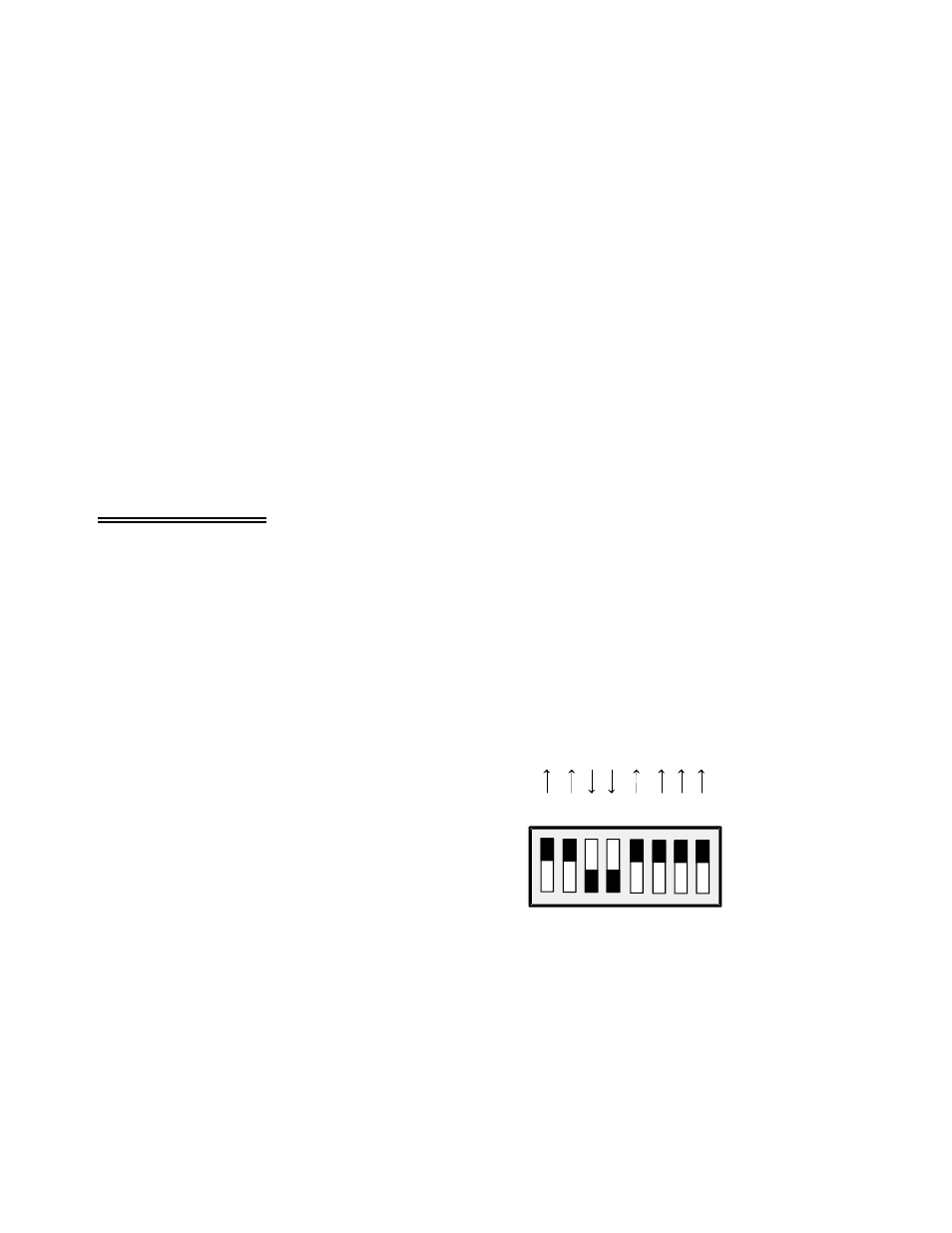
There is a switch on DIP switch block S17
(Figure 6-1) labeled X1 and X2.5. Sliding this
switch down amplifies the output of the
multiplexers by 2.5. The factory default
position (up) has a gain of 1 (unity).
The X2.5 gain switch is useful in some voltage
and bridge measurements. If you desire a
voltage gain of 2.5, 25, 250 or 2500, set this
switch down.
Figure 6-1. Board Gain
The effect of this switch is multiplicative with respect to the individual channel gains. For example, if
you have set an input channel gain to X10 and the board output gain to X2.5, the signal is amplified by
25 before it reaches the A/D board.
22