Measurement Computing CIO-EXP-GP User Manual
Page 13
To choose a switch-selectable amplification, here are the calculations you need to perform:
Divide the full range selected for the A/D board by the full range of the signal to be measured to
determine the maximum gain of the CIO-EXP board. For best resolution, use the highest gain possible
up to the calculated maximum gain.
For example, if the A/D board is to be used at a range of ±5V, the full range of the board is 10. If your
signal ranges between -0.5 volts and 0.5 volts, the full range of the signal is 1 volt. Divide 10 by 1 for a
result of 10. That is the maximum gain you can use.
If your signal is unipolar and ranges less than 0 to 5V, you would likely choose the 5V unipolar range for
the A/D board (if available). Given an input signal ranging from 0 to 0.5 volts, the full range of the
signal is 1/2 volt. Divide 5 (the full range of the A/D) by 0.5 (the full range of the signal for a result of
10. That is the maximum gain you can use.
4.4 Setting the Gain
Gain (amplification) allows you to boost your signal to take full advantage of the resolution of the A/D
converter. However, when amplifying a signal, any noise is amplified as well.
Amplification for ALL channels (board output gain) is switch selectable (S17) for X1 or X2.5.
Input amplification for EACH CHANNEL is switch selectable (GAIN switches CH0 through CH7) for
X1, X10, X100 or X1000. A user-specified gain may be set by supplying a precision resistor at position
RX### and setting the “U” option on the CH ## GAIN switch to ON.
4.4.1
Setting Board Gain
10
V
+5
CO
M
P
X2
.5
GND
0.
5V
1V
2V
4V
S17
RE
M
X1
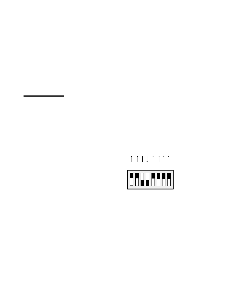
There is a switch on DIP switch block S17
labeled X1 and X2.5. Sliding this switch down
amplifies the output of the multiplexers by 2.5.
The factory default position (up) has a gain of 1
(unity). Refer to Figure 4-1.
The X2.5 gain switch is useful in some voltage
and bridge measurements. If you desire a
voltage gain of 2.5, 25, 250 or 2500, set this
switch down.
Figure 4-1. Board Output Gain Switch Location
For voltage measurements, a gain of 2500 is very high and will reduce your signal to noise ratio.
The effect of this switch is multiplicative with respect to the individual channel gains. For example, if
you have set an input channel gain to X100 and the board output gain to X2.5, the signal is amplified by
250 before it reaches the A/D board.
9