Ch4 in config, 6 setting the input configuration, Channel configuration switch - voltages – Measurement Computing CIO-EXP-GP User Manual
Page 15: 7 connecting voltage signals
Volts In
Volts Divided
Ra
Rb
INPUT
PC GROUND
OUT
PC GROUND
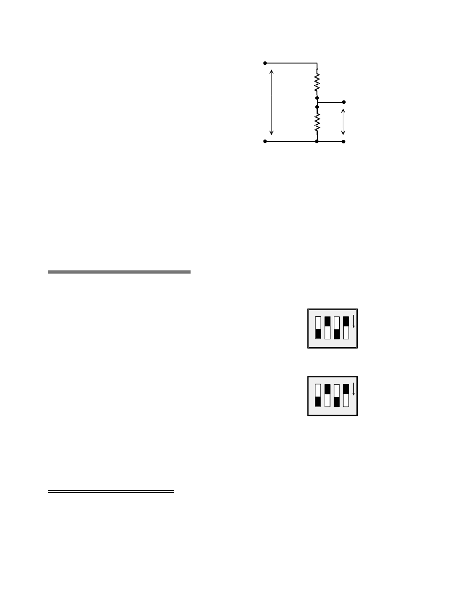
A voltage divider is constructed from a pair of
precision resistors selected according to the
equation:
Attenuation = (Ra + Rb) / Rb
See Figure 4-3 at right for the schematic of a
voltage divider.
Figure 4-3. Voltage Divider
For example, if your signal is 0 to 10V, it must be attenuated to 5V max. for an attenuation of 2:1 or
simply 2.
Using 10k resistors: 2 = (10K + 10K) /10K.
For any attenuation, pick a suitable resistor for Rb. Then use this formula to calculate Ra:
Ra = (A
−
1) x Rb
You will need to construct the voltage divider remote from the CIO-EXP-GP board.
4.6 Setting the Input Configuration
CHANNEL CONFIGURATION SWITCHES SET
VOLTAGE, THERMOCOUPLES, OR 2/4-WIRE RTDs
BOTH 4s ARE ON (DOWN), BOTH 3s ARE OFF (UP)
3
4
3
4
CH0
O
N
O
N
CH4
IN CONFIG
3
4
3
4
Channel Configuration Switch - Voltages
A channel configuration switch is associated with each
channel (Figure 4-5). The switches are used to configure the
input circuits for voltage inputs, thermocouple inputs, 2, 3, or
4-wire RTDs and bridges.
For voltage measurements on a particular channel, set the
switches labeled “4” to the ON (down) position for that
channel.
Set the switches labeled “3” in the OFF (up) position.
Figure 4-5. Channel Configuration Switches
4.7 Connecting Voltage Signals
Voltage signals can be single ended or differential, and the full scale may have to be matched to the range
of the CIO-EXP-GP and DAS board combination via amplification or attenuation. To connect a voltage
and make an accurate measurement, each of these issues must be addressed (see section 4.3).
11