Measurement Computing CIO-EXP-GP User Manual
Page 20
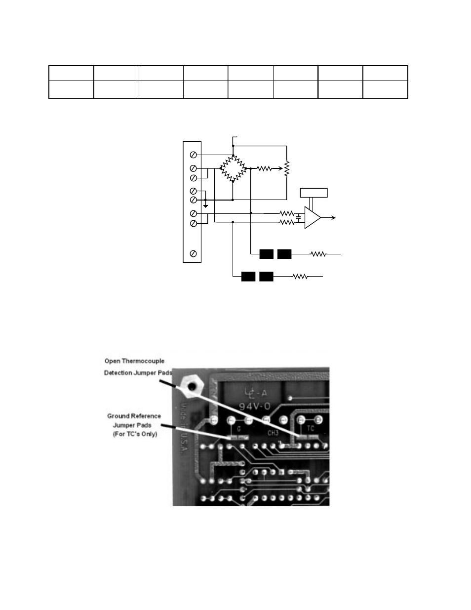
Table 5-1. 100K ohm Resistors to be Installed for OTD:
RX47
Channel 7
RX 35
Channel 5
RX 23
Channel 3
RX11
Channel 1
RX41
Channel 6
RX 29
Channel 4
RX 17
Channel 2
RX 5
Channel 0
Please solder the pads with the solder provided. It has a water soluble flux which should be washed off.
If you use another type of solder or do not wash off the flux it may affect your readings.
GAIN SW
AMP
EXCITATION VOLAGE (+)
TO CHANNEL
MULTIPLEXOR
EXCITATION. VOLTS (+)
- THERMOCOUPLE LEAD
SENSE LOW (-)
EXCITATION CURRENT (-)
EXCITATION VOLTS (-)
+ THERMOCOUPLE LEAD
SENSE HIGH (+)
EXCITATION CURRENT (+)
SENSE LOW (-)
SENSE HIGH (+)
80Hz Low
Pass Filter
-TC PULL
50 mV
100K
GND REF
10K
Figure 5-3. OTD and Ground Reference Jumper Pads - Schematic
NOTE: If you want to change the use of the input circuit to an RTD or bridge sensor, remove the solder
that closes the TC pad (and the G pad also).
Figure 5-4. OTD and Ground Reference Jumper Pads - Locations (Typ.)
16
- ACC-300 (7 pages)
- AI-EXP32 (20 pages)
- AI-EXP48 (19 pages)
- BTH-1208LS (30 pages)
- 6K-ERB08 (32 pages)
- BTH-1208LS Quick Start (4 pages)
- 6K-SSR-RACK08 (33 pages)
- BTH-1208LS-OEM (27 pages)
- CB-COM-Digital (68 pages)
- CB-7018 (68 pages)
- CB-7000 Utilities (44 pages)
- CB-7080D (74 pages)
- CB-COM-7033 (44 pages)
- CB-COM-7017 (72 pages)
- CB-COM-7024 (76 pages)
- CB-NAP-7000P (36 pages)
- CIO-DAC02/16 (16 pages)
- CIO-DAC02 (18 pages)
- CB-NAP-7000D (56 pages)
- CIO-DAC16-I (16 pages)
- CIO-DAC16/16 (20 pages)
- CIO-DAS08 (21 pages)
- CIO-DAC16 (20 pages)
- CIO-DAS08/JR (16 pages)
- CIO-DAS08/JR/16 (14 pages)
- CIO-DAS08/JR-AO (16 pages)
- CIO-DAS08-AOM (32 pages)
- CIO-DAS08-PGM (28 pages)
- CIO-DAS16/330 (34 pages)
- CIO-DAS48-I (17 pages)
- CIO-DAS16/M1 (38 pages)
- CIO-DAS48-PGA (18 pages)
- CIO-DAS800 (20 pages)
- CIO-DAS802/16 (22 pages)
- CIO-DAS6402/16 (40 pages)
- CIO-DAS-TEMP (20 pages)
- CIO-DDA06/16 (18 pages)
- CIO-DDA06/JR (17 pages)
- CIO-DIO24H (20 pages)
- CIO-DIO24/CTR3 (21 pages)
- CIO-DI192 (24 pages)
- CIO-DDA06 (21 pages)
- CIO-DIO48 (19 pages)
- CIO-DO192H (16 pages)
- CIO-DIO192 (20 pages)