Analog trigger, Analog i/o calibration, Digital i/o – Measurement Computing PCI-DAS6071 User Manual
Page 41
PCI-DAS6071 User's Guide
Specifications
41
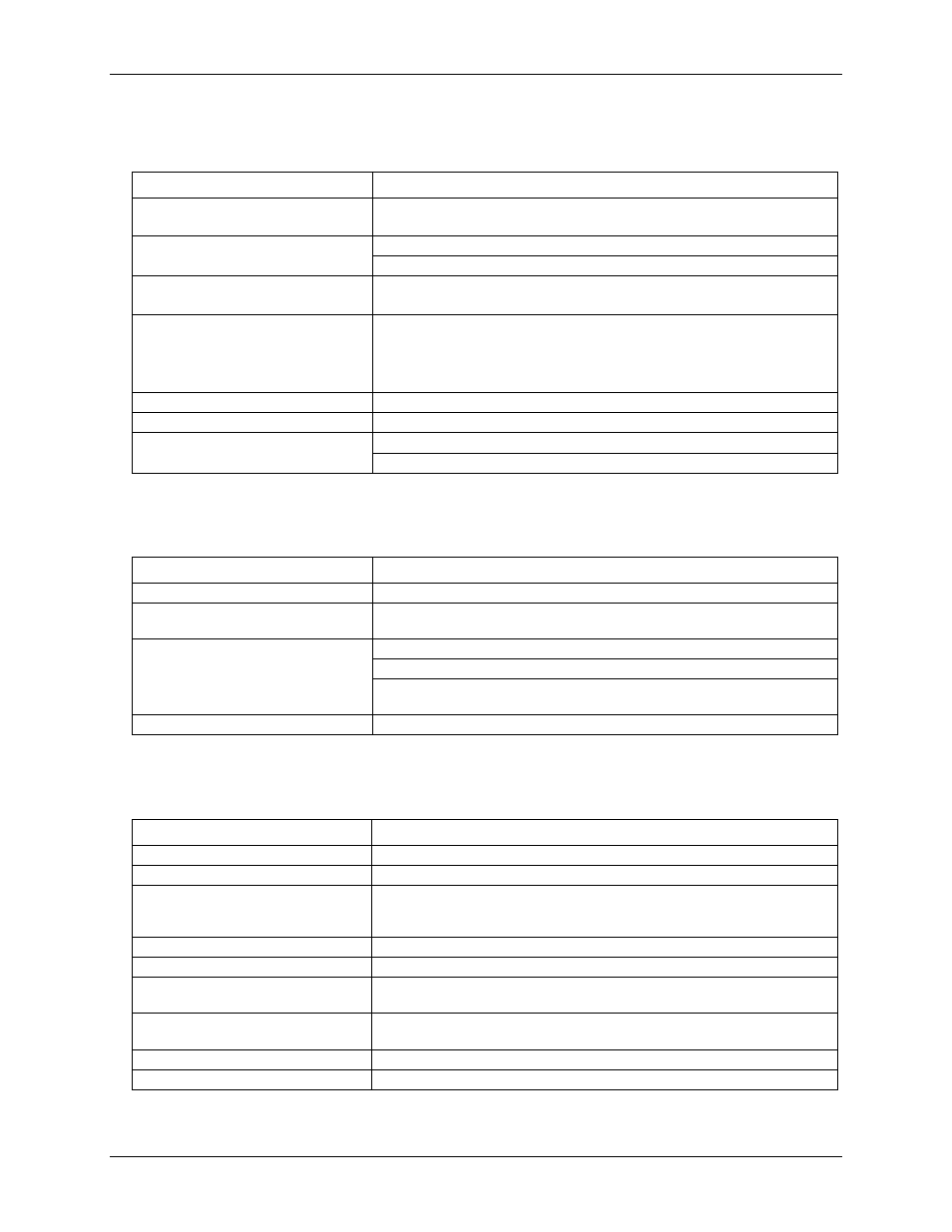
Analog trigger
Table 16. Analog trigger specifications
Parameter
Specification
Analog trigger sources
Software selectable
External:
ATRIG input
CH0 IN through CH63 IN, first channel in scan
Analog trigger levels
ATRIG input: ±10 V
CH0 IN through CH63 IN: ± Full-scale, range dependent
Analog trigger modes
External analog: Software-configurable for:
Positive or Negative slope
Analog gate modes
External analog: Software-configurable for:
Above or below reference
Positive or negative hysteresis
In or out of window
Resolution
8-bits, 1-in-256
Accuracy
±5% Full-scale range max
Bandwidth (–3 dB)
ATRIG input:
1.3 MHz
CH0 IN through CH63 IN: 2.0 MHz
Analog I/O calibration
Table 17. Analog I/O calibration specifications
Parameter
Specification
Recommended warm-up time
15 minutes
Calibration
Auto-calibration, calibration factors for each range stored on board in non-
volatile RAM.
Onboard calibration reference
DC Level: 5.000 V± 2.5 mv. Actual measured values stored in EEPROM.
Tempco: 5ppm/°C max, 2 ppm/°C typ
Long-term stability: 20 ppm,
T = 1000 hrs, non-cumulative
Calibration interval
1 year
Digital I/O
Table 18. Digital I/O specifications
Parameter
Specification
Digital type
Discrete, 5V/TTL compatible
Number of I/O
8
Configuration
8 bits, independently programmable for input or output. All pins pulled up to
+5 V via 47 K resistors (default). Positions available for pull-down to ground.
Hardware selectable via solder gap.
Input high voltage
2.0 V min, 7.0 V absolute max
Input low voltage
0.8 V max, –0.5 V absolute min
Output high voltage
(IOH = –32 mA)
3.80 V min, 4.20 V typ
Output low voltage
(IOL = 32 mA)
0.55 V max, 0.22 V typ
Data transfer
Programmed I/O
Power-up / reset state
Input mode (high impedance)