D/a convert signal, D/a external time base signal – Measurement Computing PCI-DAS6071 User Manual
Page 28
PCI-DAS6071 User's Guide
Functional Details
28
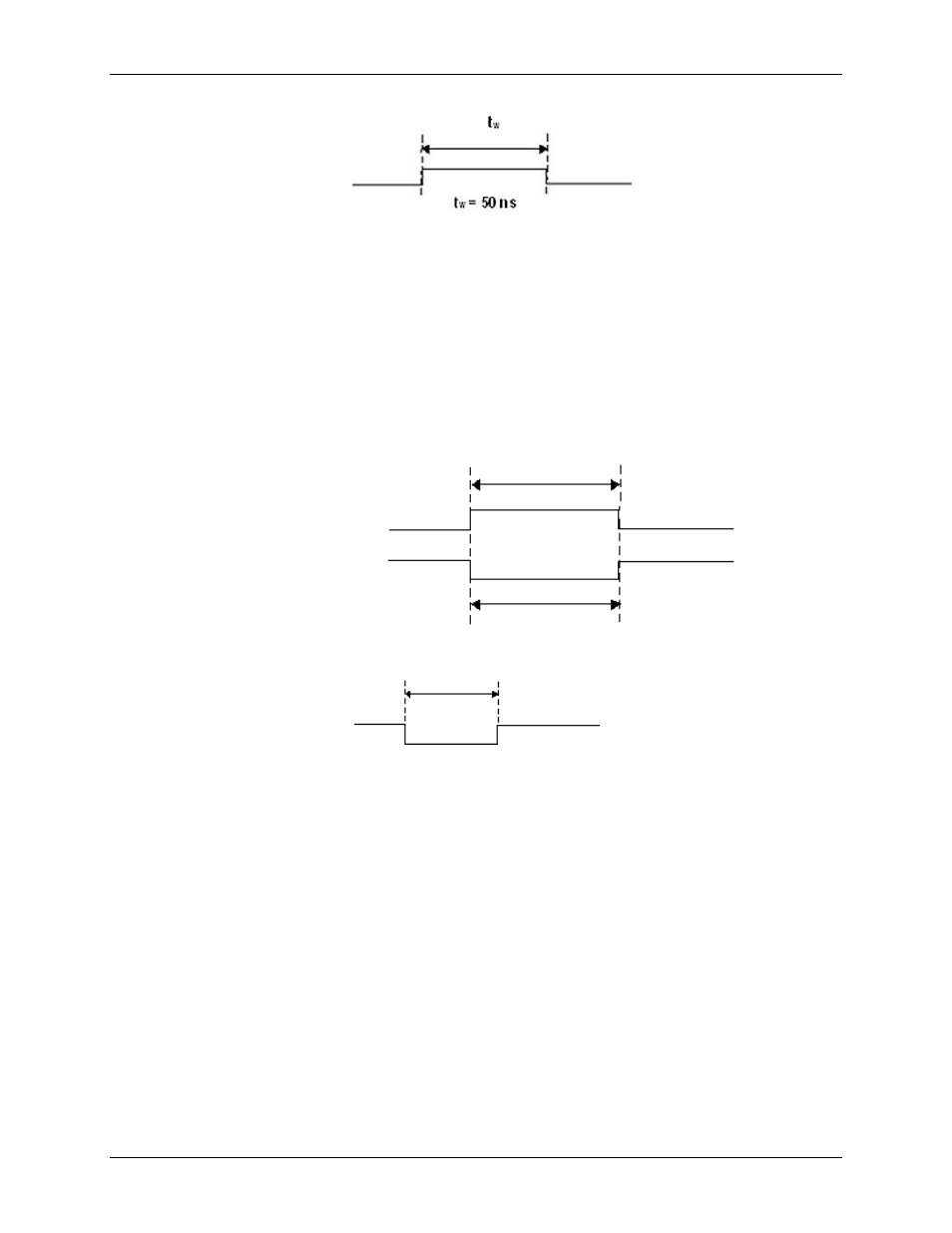
Figure 28. D/A START TRIGGER output signal timing
D/A CONVERT signal
The D/A CONVERT signal causes a single output update on the D/A converters. You can program the DAQ-
Sync DS D/A UPDATE input or any AUXIN pin to accept the D/A CONVERT signal. It is also available as an
output on any AUXOUT pin.
The D/A CONVERT input signal polarity is software selectable. DAC outputs update within 100ns of the
selected edge. The D/A CONVERT pulses should be no less than 100 µs apart.
When used as an output, the D/A CONVERT signal may be used to monitor the pacing of the output updates.
The output has a pulse width of 225 ns with selectable polarity. Figure 29 and Figure 30 show the input and
output timing requirements for the D/A CONVERT signal.
Rising Edge Polarity
t
w
t
w
= 37.5 ns minimum
Falling Edge Polarity
Figure 29. D/A CONVERT input signal timing
Figure 30. D/A CONVERT output signal timing
D/A EXTERNAL TIME BASE signal
The D/A EXTERNAL TIME BASE signal can serve as the source for the on-board DAC pacer circuit rather
than using the internal time base. Any AUXIN pin can be set programmatically as the source for this signal. The
polarity is programmable.
The maximum frequency for the D/A EXTERNAL TIME BASE signal is 20 MHz. The minimum pulse width
is 23 ns high or low. There is no minimum frequency specification.
t
w
t
w
= 225 ns