A/d external time base signal, A/d stop signal, Atrig signal – Measurement Computing PCI-DAS6071 User Manual
Page 22
PCI-DAS6071 User's Guide
Functional Details
22
A/D EXTERNAL TIME BASE signal
The A/D EXTERNAL TIME BASE signal can serve as the source for the on-board pacer circuit rather than
using the 40 MHz internal time base. Any AUXIN pin can be set programmatically as the source for this signal.
The polarity is programmable.
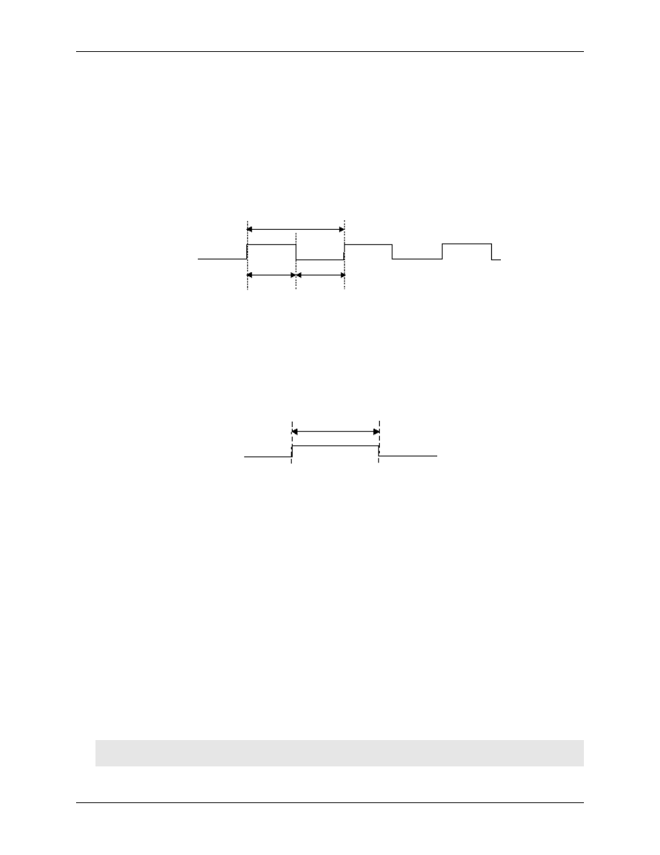
The maximum frequency for the A/D EXTERNAL TIME BASE signal is 20 MHz. The minimum pulse width
is 23 ns high or low. There is no minimum frequency specification. Figure 16 shows the timing specifications
for the A/D EXTERNAL TIME BASE signal.
t
w
t
w
=23 ns minimum
t
p
t
w
t
p
=50 ns minimum
Figure 16. A/D EXTERNAL TIME BASE signal timing
A/D STOP signal
The A/D STOP signal indicates a completed acquisition sequence. You can program this signal to be available
at any of the AUXOUT pins. The A/D STOP output signal is a 50 ns wide pulse whose leading edge indicates a
DAQ done condition. Figure 17 shows the timing for the A/D STOP signal.
t
w
t
w
= 50 ns
Figure 17. A/D STOP signal timing
ATRIG signal
In addition to standard digital trigger features, the PCI-DAS6071 also provides analog triggering capability.
When using the analog trigger, acquisitions may be started and controlled via an analog signal. There are four
trigger/gate modes available using the analog trigger feature:
Trigger – positive or negative slope
Gate – above reference or below reference
Hysteresis – positive or negative hysteresis
Window – inside or outside window
The Trigger mode is used to start an acquisition sequence. The remaining modes provide gating functions
during an acquisition sequence which start and stop the acquisition based on the gate condition.
There are two possible inputs for the analog trigger source (see Figure 18):
The first is the AUXIN0/ATRIG pin on the 100-pin I/O connector. This is a software selectable
dual-purpose pin that supports either digital or analog trigger inputs. The source selection defaults to analog
trigger on power-up and may be modified at any time using InstaCal. The input range on the ATRIG pin is
always ±10V. 8-bit DACs are used to set the HI and LO levels for the threshold(s). The threshold
resolution in this mode is 78mV per step.
Caution! Remove all analog inputs before configuring this pin as a digital input. Any voltage levels above
±15V in this configuration may cause damage to the product!