Trigger above – Measurement Computing PCI-DAS6071 User Manual
Page 23
PCI-DAS6071 User's Guide
Functional Details
23
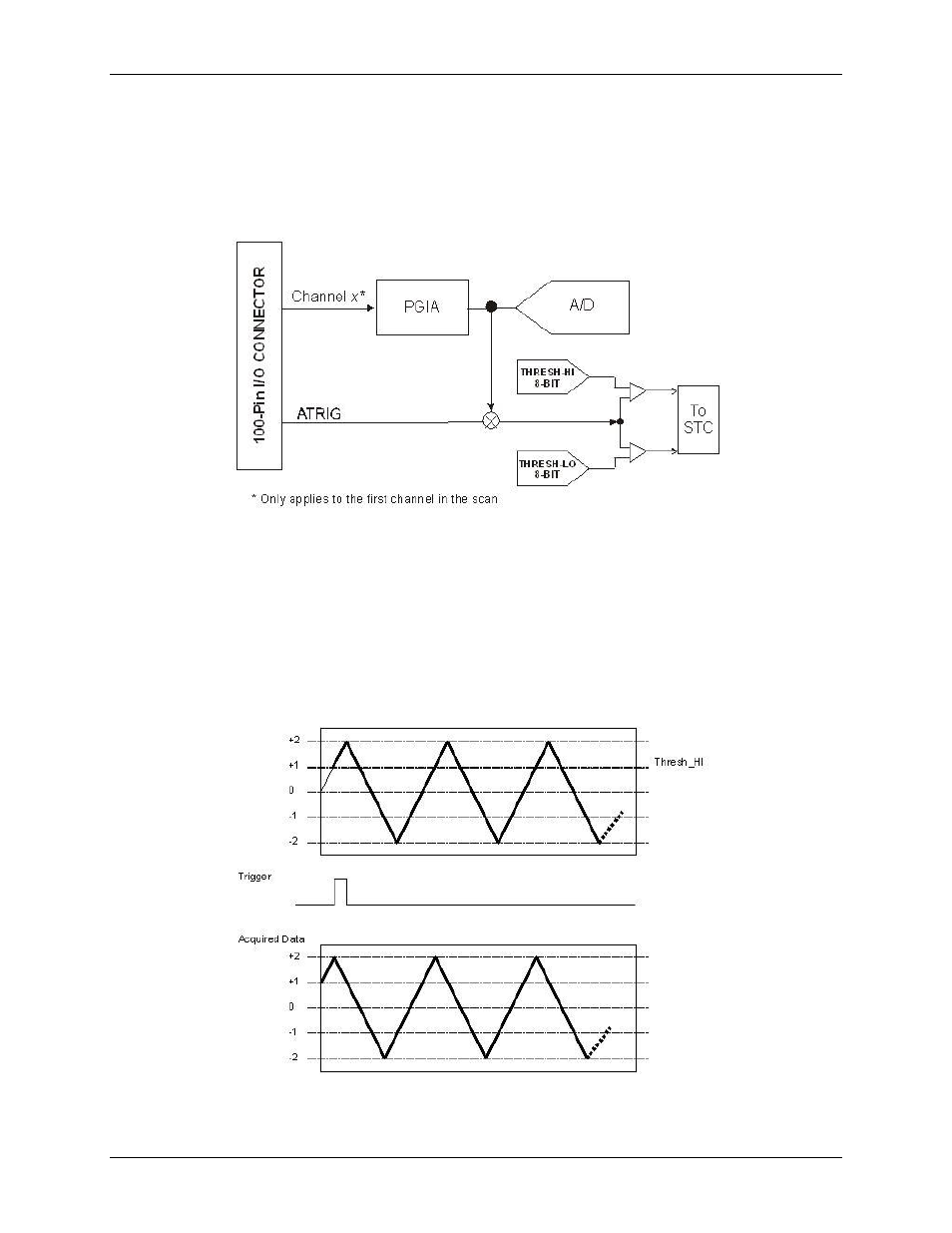
The second possible analog trigger source is the post-gain version of any one of the 64 analog inputs. In
this mode, the voltage present on the first channel in the scan may be used to initiate the acquisition
sequence.
Since the input to the analog trigger circuit has been scaled by the selected range, the effective resolution of the
thresholds is equal to the A/D's full-scale-range (±2.5V) divided by 4096. For example, the ±2.5V range allows
for 5V/4096, or 1.2 mV of threshold resolution.
Figure 18. ATRIG circuit
The next section includes a detailed description of each mode of operation. In each case, a ±2V triangle
waveform is used as the ATRIG input source. The THRESH_HI is set to 1.0V and the THRESH_LO signal is
set to -1.0V.
In the following analog trigger signal diagrams, the bold portion of the waveform indicates the data acquired for
the given ATRIG mode.
Trigger Above
The acquisition will begin when the ATRIG signal first goes above the THRESH_HI. This mode is non-
retriggerable.
Figure 19. Trigger Positive Slope