A/d stop trigger signal – Measurement Computing PCI-DAS6071 User Manual
Page 20
PCI-DAS6071 User's Guide
Functional Details
20
A/D STOP TRIGGER signal
Pre-triggered data acquisition continually acquires data into a circular buffer until a specified number of
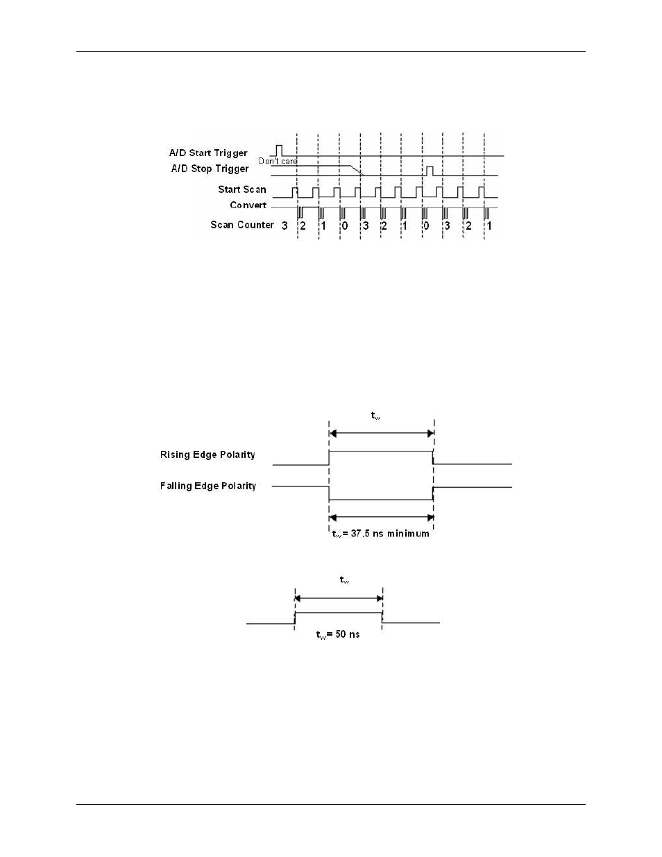
samples have been collected after the trigger event. Figure 10 illustrates a typical pre-triggered DAQ sequence.
Figure 10. Pre-triggered data acquisition example
The A/D STOP TRIGGER signal signifies when the circular buffer should stop and when the specified number
of post trigger samples should be acquired. It is available as an output and an input. By default, it is available at
AUXIN2 as an input but may be programmed for access at any of the AUXIN pins or the DAQ-Sync “DS A/D
STOP TRIGGER” input. It may be programmed for access at any of the AUXOUT pins as an output.
When using the A/D STOP TRIGGER signal as an input, the polarity may be configured for either rising or
falling edge. The selected edge of the A/D STOP TRIGGER signal initiates the post-triggered phase of a pre-
triggered acquisition sequence.
As an output, the A/D STOP TRIGGER signal indicates the event separating the pre-trigger data from the post-
trigger data. The output is an active high pulse with a pulse width of 50 ns. Figure 11 and Figure 12 show the
input and output timing requirements for the A/D STOP TRIGGER signal.
Figure 11. A/D STOP TRIGGER input signal timing
Figure 12. A/D STOP TRIGGER output signal timing