K-Patents PR-01-S User Manual
Page 95
INSTRUCTION MANUAL FOR K-PATENTS PR-01-S (-AX/FM/CS)
DOCUMENT/REVISION No. INM 1/14
Effective: May 15, 2009
93
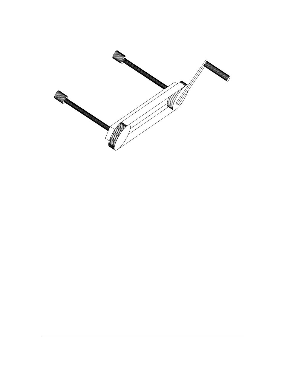
To turn the nuts on the two force bars synchronously to get a straight guided movement of the sensor, a Crank
Unit (CR) is supplied, Figure 11.14.
Figure 11.14
Crank (CR) for retractor HIMP-2 and HIMP-3.
To complete the steam wash system, add according to Figures 11.12 and 11.31/11.32:
– steam valve
– necessary piping to connect the steam input
– steam trap
A steam valve and trap assembly PR-3340.
11.2. MOUNTING
See Appendix A, “Installation of the Isolation valve HIMP-2/HIMP-3 to the process pipe”, p. 105, for
mounting instructions.
See Appendix B, “Inserting the sensor to the isolation valve HIMP-2/HIMP-3”, p. 113, on how to insert a
sensor into the process line.
See Appendix C, “Retracting the sensor from the isolation valve HIMP-2/HIMP-3”, p. 117, on how to
retract a sensor from the process line.