K-Patents PR-01-S User Manual
Page 105
INSTRUCTION MANUAL FOR K-PATENTS PR-01-S (-AX/FM/CS)
DOCUMENT/REVISION No. INM 1/14
Effective: May 15, 2009
103
12.4. BARRIER POWER UNIT PR-7070
The Barrier power card PR-7040 accepts a 24 V DC input from the Indicating transmitter and provides the
following functions:
1. 24V DC fused supply to Zener barrier Z728
2. 12V DC fused supply to Zener barrier Z965
3. Automatic gain control (AGC) and line driver for the signal from Optobarrier PR-7075. The output to
the Indicating transmitter is an RS 485 signal.
Fuses on the Barrier power card PR-7040 as follows:
1. F1 100mA MSF/Schurter
2. F2 100mA MSF/Schurter
3. F3 63mA MSF/Schurter
12.5. FUNCTIONAL DESCRIPTION
The Information and Power flow in the intrinsically safe Sensor is in figure 6.50b. The Indicating
transmitter is identical to the standard non-intrinsic version, see Figure 6.21.
The Sensor is functionally identical to the standard Sensor, but the Image detector module is made on a
separate intrinsically safe circuit. Thus the Image Digitizer card is divided into two separate intrinsically
safe circuits, see Figure 12.52. (See also Figure 6.50 and 6.52).
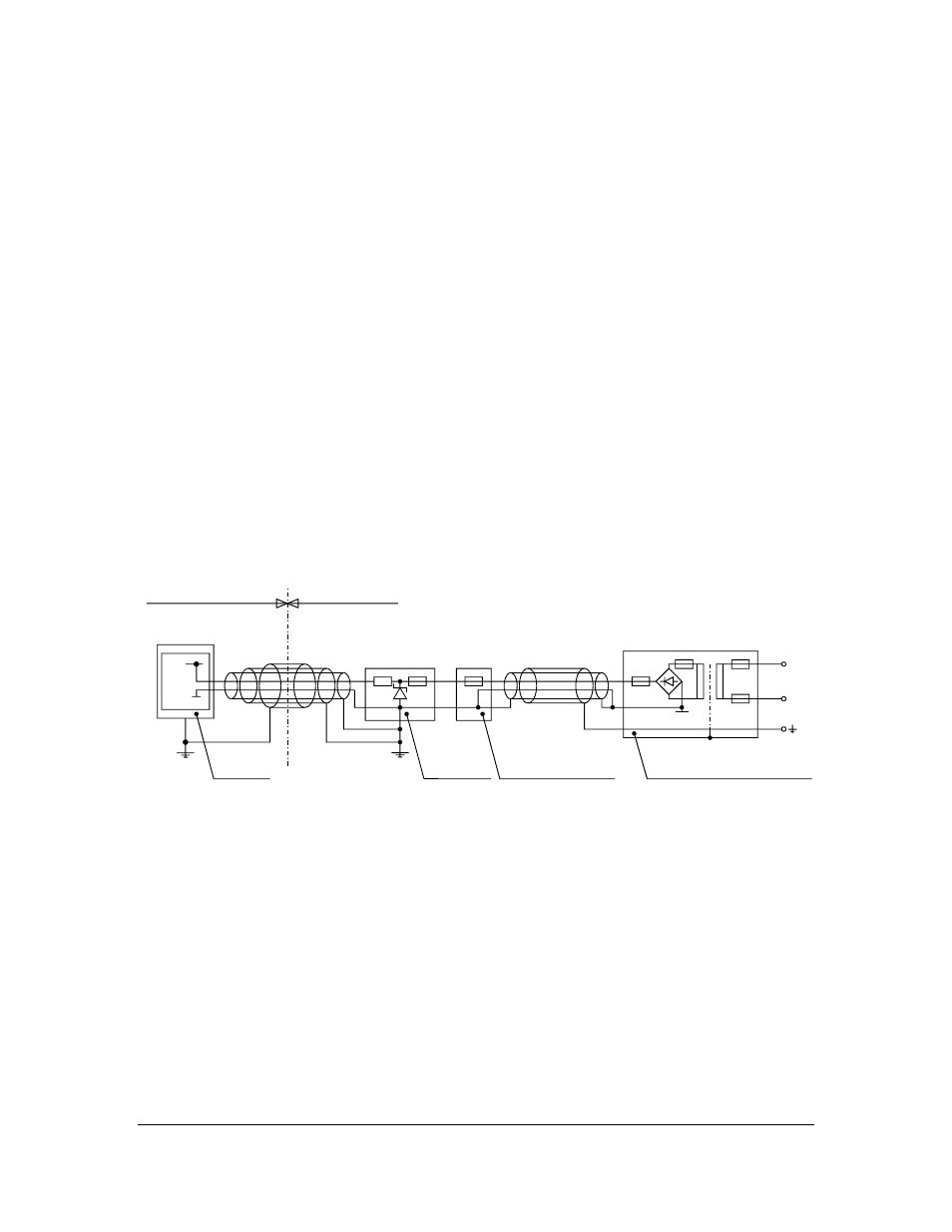
The Figure 12.51 shows the earth connections. The Figure 12.53 describes the sensor internal wiring.
R1
F1,2
F1
F5
F4
F1
F2
HAZARDOUS AREA
SAFE AREA
SENSOR
BARRIERS
BARRIER POWER
INDICATING TRANSMITTER
L1
N
+
0
0
0
Figure 12.51
Earth connections.