K-Patents PR-01-S User Manual
Page 28
INSTRUCTION MANUAL FOR K-PATENTS PR-01-S (-AX/FM/CS)
DOCUMENT/REVISION No. INM 1/14
Effective: May 15, 2009
26
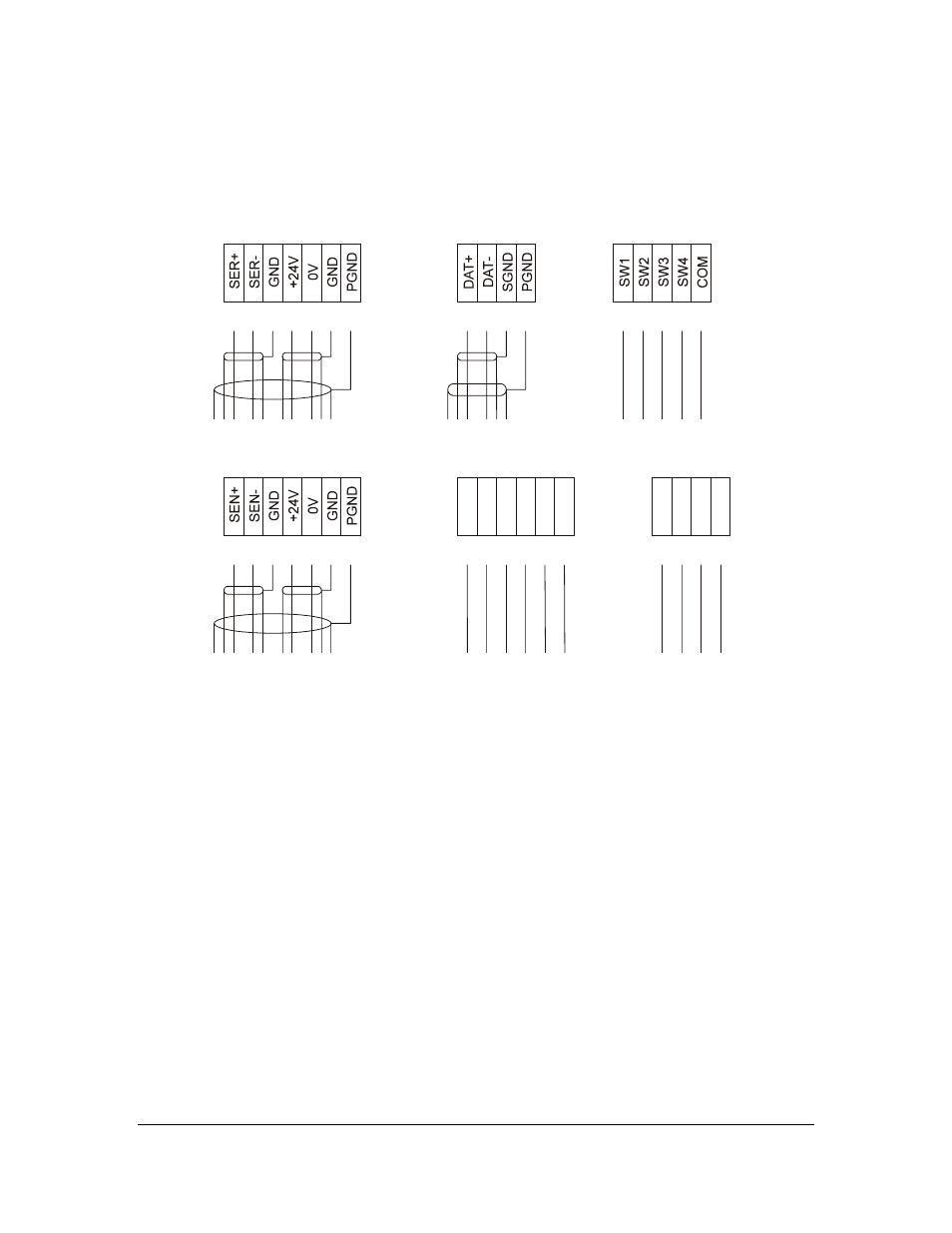
Terminal strip:
The rest of the connections are made to the terminal strip, Figure 3.61.
1
8
2
9
3
10
4
11
27
43
47
29
45
49
15
5
12
28
44
48
30
46
50
31
16
6
13
17
7
14
18
SENSOR
SERIAL BUS
RS-485
SWITCHES
RLY1 RLY2
25 26
4-20mA
+ -
Figure 3.61
Terminal strip.
Sensor:
At the Indicating transmitter end of the interconnecting cable has leads numbered from 1 to 7 to be
connected to the terminals with the same numbers. The sensor end of the interconnecting cable is
terminated by a plug, Figure 6.22. The interconnecting cable may be shortened or lengthened up to the
limit specified, Section 2.2. The interconnecting cable should be installed in a separate metal conduit. For
cable specifications, see Section 2.2.
Current output:
The terminal 25 is plus (+) and 26 minus (-) for the 4-20 mA output signal. The signal is specified in
Section 2.2.
Recorders, controllers, indicators etc. shall be connected to form a closed current loop, starting from
terminal 25 passing each device, in at plus and out at minus, ending at terminal 26. Be careful not to exceed
the specified load resistance.
The range of the output signal can be set to 0-20 mA from the keyboard (Section 2.8), select
Calibrate/Output signals/Current output/Range.