K-Patents PR-01-S User Manual
Page 41
INSTRUCTION MANUAL FOR K-PATENTS PR-01-S (-AX/FM/CS)
DOCUMENT/REVISION No. INM 1/14
Effective: May 15, 2009
39
1.30
1.35
1.40
1.45
1.50
1.55
1.60
50 °
57 °
R.I.
40
0
10
20
30
50
60
70
80
BRIX
Figure 5.60
Sensor rangeability.
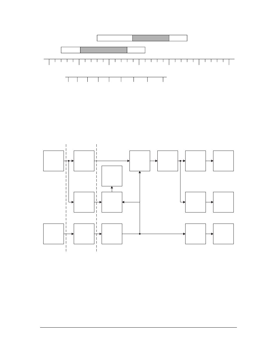
5.7. EPROM PARAMETERS
How to enter the calibration parameters into the non-volatile EPROM memory is described in Section 2.8. The
factory settings are found in the DELIVERY DATA SHEET. Figure 5.70 shows how the microprocessor
program is using the parameters.
BIAS
GAIN
CUBE
SQUARE
TNM
TCOEFF
TEMP TCADJ.
CONC TCADJ.
SQUARE TEMPCO
DAMPING
TEST
TEMP
UNIT
DECIMALS
ZERO
SPAN
HOLD
UNIT
°C / °F
CONC.
DISPLAY
OUTPUT
mA
TMPC 0
TMPC 1
RI-BIAS
RI-GAIN
RI-CUBE
RI-SQUARE
STAN-
DARD
RI
DISPLAY
FIXED
RI
TEMP.
COMP.
TBIAS
TEMP.
DISPLAY
TEMP °C
DATA
SENSOR
ADAPTION
Figure 5.70
Calculation flow diagram.
The ENTER procedure contains a check of the EPROM parameters format. A number outside the range
limits cannot be entered. Only if the range limits of a parameter contain a decimal point, the parameter may
contain a decimal point. For some parameters the number of characters is limited (character = digit,
decimal point or minus sign).
Indicating transmitter exchange:
If the Indicating transmitter is exchanged, then all parameters and configuration determinations have to be
changed.