See page 32 for all toggle dimensions – Harken 7415.15S MKIV Hydraulic Jib Reefing & Furling User Manual
Page 33
MKIV Hydraulic Unit 5
33
Appendix
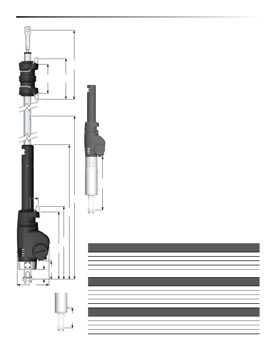
Dimensions/Sailmakers's Instructions
Luff Length
Note offsets above and below sail.
A shorter luff may be required if a halyard restrainer is used or
an additional toggle assembly is used to raise unit.
If luff of sail is not long enough to put halyard swivel near top
of headstay foil, a pendant must be added. See page 25.
Tack Setback
Note setback for tack shackle and cut sail accordingly.
Luff Tape Size
Unit 5H requires #6 (
6
/
32
" or 5 mm) luff tape.
Luff Tape Length
Cut off top of luff tape so it is 24 to 36" (600 to 1000 mm) below head
of sail. This allows head to lag behind rest of sail to help flatten sail.
It will also help head to roll more smoothly.
Note feeder height and extend bottom of luff tape downward so it is
below feeder. This will prevent luff tape from catching in feeder as
sail is lowered.
Tack and Head Lashing
Choose high strength low stretch line to lash head and tack to
fittings. Use specialty knots such as a triple fisherman's knot. See
knot tying resources at www.harken.com/knots.
Sun Cover
Sun covers may be installed on either side of sail. Be sure to match
other sails in the customer's inventory.
I
K
G
I
H
D
C
B
A
J
F
E
See page 32
for all toggle
dimensions.
A
B
C*
D**
E
Max
E
Min
in
mm
in
mm
in
mm
in
mm
in
mm
in
mm
7415.25 1
1
/
8
Std
10
1
/
2
267
16
3
/
4
425
31
1
/
2
800
6
150
62
13
/
16
1596.19
—
—
7415.25 1
1
/
4
Std
10
1
/
2
267
16
3
/
4
425
31
1
/
2
800
6
150
63
8
/
16
1613
—
—
7415.26 1
1
/
8
Cylinder
10
1
/
2
267
16
3
/
4
425
31
1
/
2
800
6
150
87
15
/
16
2234
81
15
/
16
2081
7415.26 1
1
/
4
Cylinder
10
1
/
2
267
16
3
/
4
425
31
1
/
2
800
6
150
88
5
/
8
2251
82
5
/
8
2098
* Approximate, will vary according to rigging used. Assumes about a 80 mm offset for each lashing.
** Approximate measurement from boltrope to lashing bearing point.
F
Max
F Min
G Max***
G Min***
H Max
H
Min
in
mm
in
mm
in
mm
in
mm
in
mm
in
mm
7415.25 1
1
/
8
Std
41
1042
—
—
26
1
/
16
662
—
—
23
11
/
16
602
—
—
7415.25 1
1
/
4
Std
41
11
/
16
1059
—
—
26
3
/
4
679
—
—
24
1
/
2
619
—
—
7415.26 1
1
/
8
Cylinder
66
1
/
8
1679
60
1
/
8
1527
51
15
/
16
1319
45
15
/
16
1167
48
13
/
16
1239
42
13
/
16
1087
7415.26 1
1
/
4
Cylinder
66
13
/
16
1697
60
13
/
16
1544
52
5
/
8
1337
46
5
/
8
1184
49
1
/
2
1257
43
1
/
2
1104
*** Assumes a 80 mm offset for lashing.
I
Max
I
Min
J
Max
J
Min
K
in
mm
in
mm
in
mm
in
mm
in
mm
7415.25 1
1
/
8
Std
6
5
/
8
168
—
—
3
5
/
8
91.8
—
—
10
3
/
8
263.67
7415.25 1
1
/
4
Std
7
1
/
4
185
—
—
4
5
/
16
108.99
—
—
10
3
/
8
263.67
7415.26 1
1
/
8
Cylinder
31
7
/
16
799
25
1
/
2
647
15
1
/
8
#
384#
9
1
/
8
232
10
3
/
8
263.67
7415.26 1
1
/
4
Cylinder
32
1
/
8
816
26
1
/
8
663
15
13
/
16
# 402#
9
13
/
16
2496
10
3
/
8
263.67
# Height of cylinder threaded hydraulic port.
J