Greenheck Microprocessor Controller (474706 IOM) TAP v1.04 June 2011 (ERCH, ERH, APEX, VER, ERT) User Manual
Page 13
13
DDC Controller for Tempered Air Products
T
his
screen
displays
The
minimum
and
maximum
supply
air
TemperaTure
limiTs
.
This screen only appears if the unit is connected to a room temperature sensor.
The supply air temperature will be controlled within the Supply Min and Supply
Max limits to maintain room temperature set point.
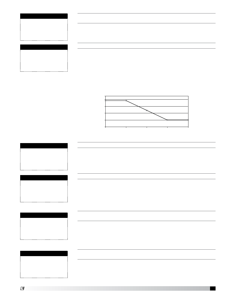
T
hese
parameTers
dicTaTe
The
operaTion
of
The
ouTdoor
air
reseT
funcTion
.
This screen does not appear when a room temp sensor is wired to the controller.
The controller monitors the outdoor air temperature and adjusts the desired
supply temperature accordingly. For example, when the outdoor air is below
60°F, the controller will change the Supply set point to 72°F. If the outdoor
air is above 70°F, the controller will change the Supply set point to 55°F. If
the outdoor air temperature is between 60°F and 70°F, the Supply set point
changes according to the outdoor air reset function. A visual representation of
the outdoor air reset function is shown below.
T
his
screen
displays
The
supply
air
seT
poinT
as
seT
by
a
bms.
This screen appears if the unit has BMS communications and set point source is
set to BMS.
See Set Point Source screen in this menu to allow BMS to determine set point.
T
he
conTroller
will
lockouT
cooling
when
The
ouTdoor
air
TemperaTure
is
below
The
cooling
lockouT
seT
poinT
. (f
acTory
d
efaulT
= 55°f)
This screen only appears if the unit the unit is equipped with cooling.
There is a built in hysteresis of 2°F which prevents the cooling from short
cycling. The hysteresis is similar to a dead-band above and below the lockout
set point. (Example: If Lockout = 55°F, cooling is locked out below 53°F and
enabled above 57°F outside air temperature.)
T
he
conTroller
will
lockouT
heaTing
when
The
ouTdoor
air
TemperaTure
is
above
The
heaTing
lockouT
seT
poinT
. (f
acTory
d
efaulT
= 70°f)
This screen only appears if the unit the unit is equipped with heating.
There is a built in hysteresis of 2°F which prevents the heating from short
cycling. The hysteresis is similar to a dead-band above and below the lockout
set point. (Example: If Lockout = 70°F, heating is locked out above 72°F and
enabled below 68°F outside air temperature.)
T
his
screen
displays
The
TemperaTure
seT
poinTs
for
The
cooling
coil
.
This screen only appears if the unit is equipped with cooling.
The Normal mode set point is the after coil temperature the unit will maintain
under standard operation, when in cooling. If a humidistat was provided
with the unit, the Dehumidify set point is the temperature the cooling coil will
discharge on a call for dehumidification. The Active set point is the cooling coil
discharge temperature the unit is currently trying to maintain.
Supply Reset Limits
Supply Min:
55.0°F
Supply Max:
90.0°F
Supply Air Reset
Outside:
Supply
60.0°F - - >
72.0°F
70.0°F - - >
55.0°F
Supply Set From BMS
BMS interface:
##.#°F
Set pt min:
55.5°F
Set pt max:
90.0°F
Cold Coil Set Point
Normal Mode:
55.0°F
Dehumidify:
50.0°F
Active set pt:
55.0°F
Heater Lockout
Lockout heater when outside
above:
70.0°F
Hysteresis:
2.0°F
Cooling Lockout
Lockout cooling when outside
below:
55.0°F
Hysteresis:
2.0°F
Outdoor Air Reset Function
49°
55°
61°
67°
73°
55°
60°
65°
70°
75°
Outside Air Temperature (°F)
Supply Air Set Point
(°
F)
®