Pid block diagram, Table 8.16 pid parameters, An internal test parameter – Flowserve 400MD Logix User Manual
Page 52
Index
Origin
Name
Size
Date Type
Default Value
73
MFG
FUTURE1
4
Simple
FLOATING_POINT
0
74
MFG
PID_BLOCK_TEST
8
Array
UNSIGNED8
0,0,0,0,0,0,0,0
Table 8.15 Flowserve PID Parameters
Parameter Name
Description/Parameter Contents
PID_FORM
Configuration parameter specifies the IDEAL or ROBUST PID equation to be used: IDEAL PID (default). Non-Interactive form of
a three mode control equation that provides Proportional, Integral and Derivative (PID) control action. Linear and non-linear gain
parameters are available. ROBUST PID. The same as Ideal PID. Additionally, the equation supports a user-config ured lag filter
applied to calculated output value. (See OUT_LAG parameter.) Linear and non-linear gain parameters are available.
ALGO_TYPE
Configuration parameter specifies algorithm type which can be A, B, or C: Type A equation where Proportional, Integral and
Derivative act on ERROR. Type B equation where Proportional and Integral act on ERROR and Derivative acts on PV. Type C
equation where Integral acts on ERROR and Proportional and Derivative act on PV.
OUT_LAG
GAIN_NLIN
Time constant of single exponential LAG filter applied to the OUT parameter (primary output). Units (in seconds). For ideal PID
equation the lag filter is fixed at 1/16 and cannot be configured.
Dimensionless gain factor. When the gain factor is multiplied by absolute value of the error and added to the linear GAIN, the
result is a gain response which is proportional to the deviation. Default is zero, resulting in no response due to non-linear gain
action.
GAIN_COMP
The composite gain quantity including both linear and non-linear gain parameters. (Read-only parameter.)
Table 8.16 PID Parameters
Parameter Name
Description/Parameter Contents
ERROR_ABS
Absolute value of the difference between PV and working set-point. (Read only parameter.)
WSP
Working set-point. This is the set-point value after absolute and rate limits have been applied.
Deviation alarms are computed on this value. (Read only parameter.)
PID_BLOCK_TEST
An internal test parameter.
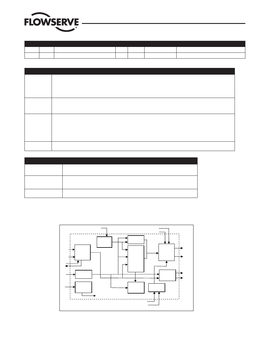
PID Block Diagram
Figure 8.4 is a block diagram showing the key components of the PID control function block.
Figure 8.4 PID Control Block
Setpoint
SP_RATE_DN
SP_RATE_UP
SP HI LIM
SP_LO_LM
SHED_OPT
Mode Select
BKCAL_OUT
GAIN
RESET
RATE
BAL_TIME
PID Control
CAS_IN
RCAS_IN
IN
RCAS_OUT
BKCAL_IN
Output
OUT_ HI_LIM
OUT_LO_ LIM
BAL_T IME
OUT
TRK_SCALE
Output Track
TRK_IN_D
TRK_VAL
SP
PV_FTIME
PV Filter
PV
BYPASS
Bypass
HI/LO
DEV
Alarm
FF_SCALE
FF_GAIN
Feed Forward
ROUT_IN
ROUT_OUT
WSP
Backward
Path Outputs
Target &
Permitted
Mode
Actual &
Normal
Mode
FF_VAL
PID_FORM
ALGO_TYPE
OUT_LAG
GAIN_NLIN
GAIN_COMP
ERROR_ABS
BKCAL_HYS
Logix 3400MD Digital Positioner LGENIM3405-02 11/13
52