7 md transducer block – Flowserve 400MD Logix User Manual
Page 42
•
Calibration Auto: allows the user to specify the auto calibration (default) or to enter into a job calibration mode.
LX_SPI_STATUS_FLAGS Should a loss of communications occur between the fieldbus card and positioner card this parameter sets the fail mode
of the valve. Nothing selected will cause the positioner to hold the last known command should a loss of communications occurs.
STROKE_TIME_UP: Allows the user to limit the stroking speed of the positioner. Input the number of seconds for the desired opening stroke
speed. Disable this feature by writing 0 to the variable.
STROKE_TIME_DN: Allows the user to limit the stroking speed of the positioner. Input the number of seconds for the desired closing stroke
speed. Disable this feature by writing 0 to the variable.
CURVE_SELECT: This parameter allows the user to select what type of characterization curves the positioner will use. The selections are Equal
Percent, Quick Open, or Custom. If Custom is selected, the parameters CURVEX and CURVEY must be initialized.
NVRAM_WRITE_CYCLES: This is a diagnostic parameter that allows the user to monitor the number of times the NVRAM is written to. This
can be a useful diagnostic tool for checking if the host system is writing to the Fieldbus board memory too often. This is often a configura-
tion error in the host system setup. Excessive write cycles can cause configuration upsets and possible communications slowdowns and
errors. It also will shorten the operational life of a Fieldbus device by exceeding the finite number of write cycles NVRAM chips can be used
reliably to. These devices typically have a minimum 10,000,000 write cycle endurance. Even though this is a very high number that would typically
never be reached during the operational life of the device, a misbehaving host configura tion routing could drive up the number of write cycles very quickly,
and should be corrected as all devices in the configuration will be adversely affected by this continuous download.
8.7 MD Transducer Block
The MD Transducer block contains the parameters used by the advanced and pro model of the Logix 3400MD. These parameters are used for
diagnostics and error detection of the system.
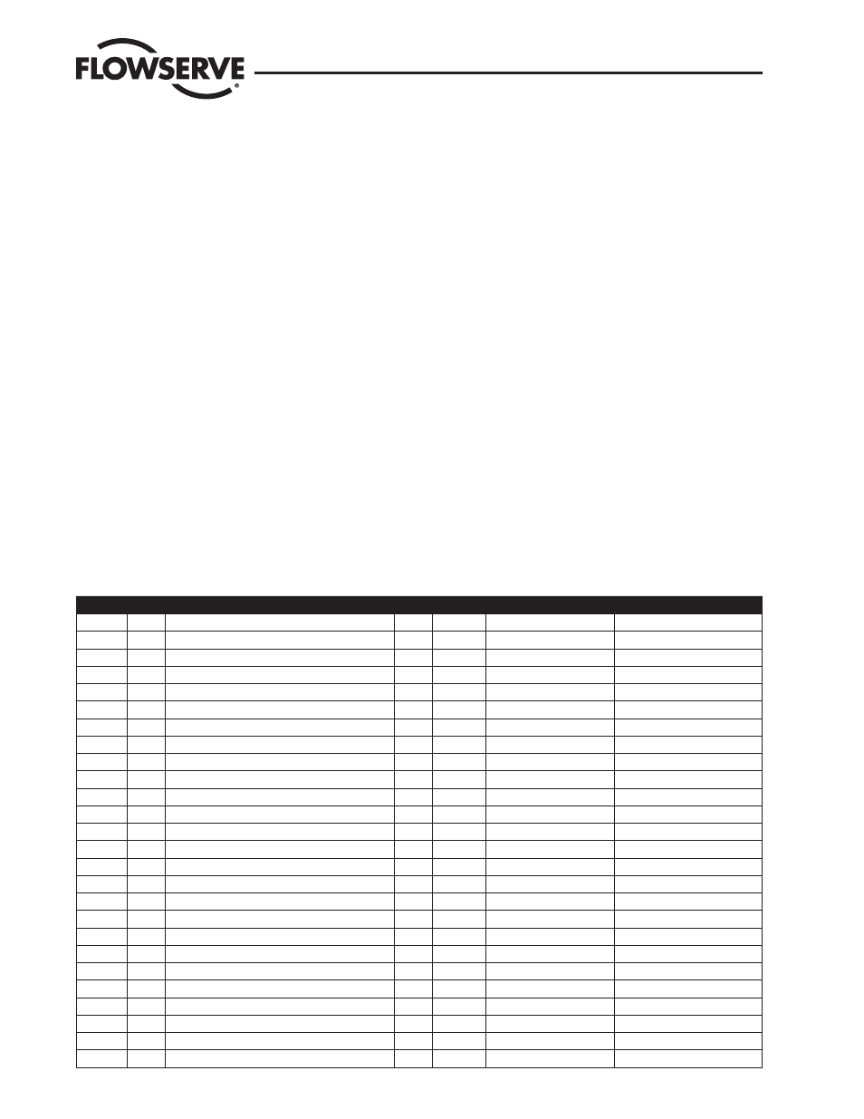
Table 8.8 Transducer Block Parameters
Index
Origin Name
Store Date Type
Default Value
0
STND XDTB_MD
SRW
Record
BLOCK
0
1
STND ST_REV
SR
Simple
UNSIGNED16
1
2
STND TAG_DESC
SRW
Simple
OCTET_STRING
“7 “
3
STND STRATEGY
SRW
Simple
UNSIGNED16
2
4
STND ALERT_KEY
SRW
Simple
UNSIGNED8
4
5
STND MODE_BLK
SRW
Record
MODE
0x01;0x01;0x11;0x10
6
STND BLOCK_ERR
R
Simple
BIT_STRING
0
7
STND UPDATE_EVT
RW
Record
ALARM_EVENT
0;0;0,0;0;0;0;0
8
STND BLOCK_ALM
RW
Record
ALARM_DISC
0;0;0,0;0;0;0;0;0;0
9
STND TRANSDUCER_DIRECTORY
NR
Array
UNSIGNED16
0
10
STND TRANSDUCER_TYPE
NR
Simple
UNSIGNED16
106
11
STND XD_ERROR
R
Simple
UNSIGNED8
0
12
STND COLLECTION_DIRECTORY
NR
Array
UNSIGNED32
0
13
MFG
LD_MD_MODE
R
Simple
UNSIGNED8
0
14
MFG
MECHANICAL_STATUS
R
Simple
BIT_STRING
0
15
MFG
MECHANICAL_MASKING
NRW
Simple
BIT_STRING
0
16
MFG
VALVE_TRAVEL_DISTANCE
R
Simple
FLOATING_POINT
0
17
MFG
VALVE_TRAVEL_HIGH_START
RW
Simple
FLOATING_POINT
0
18
MFG
VALVE_TRAVEL_HIGH_END
RW
Simple
FLOATING_POINT
0
19
MFG
VALVE_TRAVEL_PERCENT_YELLOW
NR
Simple
FLOATING_POINT
0
20
MFG
VALVE_CYCLE_COUNT
R
Simple
UNSIGNED32
0
21
MFG
VALVE_CYCLE_HIGH_START
RW
Simple
UNSIGNED32
0
22
MFG
VALVE_CYCLE_HIGH_END
RW
Simple
UNSIGNED32
0
23
MFG
VALVE_CYCLE_PERCENT_YELLOW
NR
Simple
FLOATING_POINT
0
24
MFG
PST_TIME_BREAKAWAY
NR
Simple
FLOATING_POINT
0
25
MFG
PST_PRESSURE_DIFF
R
Simple
FLOATING_POINT
0
Logix 3400MD Digital Positioner LGENIM3405-02 11/13
42