Ao block diagram, Clearing block configuration errors, Mode-restricted write operations – Flowserve 400MD Logix User Manual
Page 46: Simulate, readback and pv determination
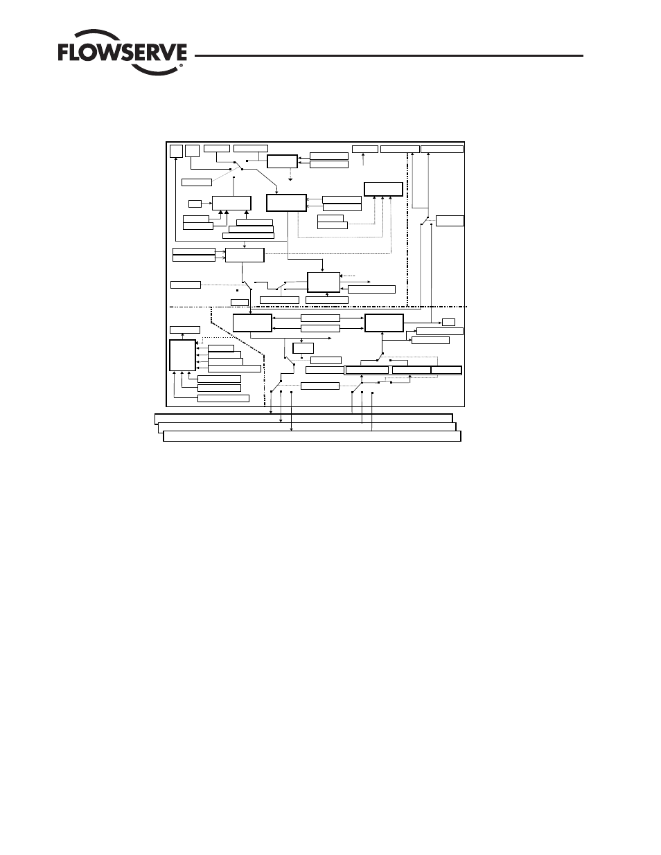
AO Block Diagram
Figure 8.3 is a block diagram showing the key components of the AO function block.
Figure 8.3 AO Function Block Diagram
Clearing Block Configuration Errors
Block configuration errors prevent the block from leaving OOS mode. The parameter BLOCK_ERR will show whether a block configuration error
is present. Table 10.7 is a list of parameters that can cause the status of CONFIGURATION ERROR to be set in the AO BLOCK_ERR parameter.
NOTE: CONFIGURATION ERROR can only be cleared if the function block is being executed. One way of determining block execution is by per-
forming a series two or three reads of the BLOCK_TEST parameter and confirming that the first byte of the parameter is incrementing. This will
work if the execute rate is fast relative to the speed of reading BLOCK_TEST. A very slowly executing block may not appear to execute because
block parameters are updated only when the block executes.
Mode-restricted Write Operations
Table 8.7 lists the AO block parameters which may be write restricted based upon the block’s mode. Listed in the table are the TARGET and/or
ACTUAL modes required for the write to be accepted. Other limitations listed in the last column must also be met.
SIMULATE, READBACK and PV Determination
In the AO Function Block, these three parameters provide the values and status of the actuator position, where SIMULATE (or optionally OUT)
generates the READBACK parameter and READBACK is then re-scaled to produce the PV.
The following sub-sections describe each of these parameters.
SIMULATE Parameter SIMULATE is the interface parameter between the AO and the Transducer Function Blocks. Each time the AO block ex-
ecutes, SIMULATE.TRANSDUCER is updated with the FINAL_POSITION_VALUE from the transducer block.
When the SIMULATE.ENABLE is FALSE, SIMULATE.TRANSDUCER is copied into SIMULATE. SIMULATE. When SIMULATE.ENABLE is TRUE,
SIMULATE.SIMULATE is not updated with SIMULATE.TRANSDUCER and the user may write a value and status to SIMULATE.SIMULATE.
AO Block Diagram
Figure 8.3 AO Function Block Diagram
Transducer Block 1
Transducer Block 2
OUT
Convert
PV SCALE
MODE
Select
SP RATE UP
ACTUAL
TARGET
PERMITED
PV
CAS IN
RCAS IN
Setpoint
Limiting
SP RATE DN
SP HI LIM
SP LO LIM
SP
(Read)
XD SCALE
FaultState
Check
FSTATE TIME
FSTATE_VAL
BKCAL OUT
RCAS OUT
SIMULATE:
TRANSDUCER
SIMULATE
ENABLE
READBACK
PV
Convert
U
SE PV
FOR BKCAL
BLOCK ALM
SHED OPT
UPDATE EVT
STATUS OPTS
AUTO
RCAS
F
ROM
O
UT
C
ONVERT
LO
AUTO
MAN
FaultState to Value
Rate
Limiting
Last SP
FSTATE
VALUE
MAN
LO
SP
(Write)
Setpoint
Tracking
PV
TARGET
ACTUAL
WSP
Status
Calculation
Invert
Incr. to Close
fstate: Active
Time OUT
Timer
SHED RCAS
Targ to MAN on Bad IN
CHANNEL
Transducer Block n
SHED OPT
OUT
T
O
O
UT
P
ARAMETER
CAS
ACTUAL
ACTUAL
TARGET
ACTUAL
SP Track Ret. Tgt
SP PV Track in Man.
SP PV Track LO IMAN
RCAS timeout
RCAS timeout
RCAS timeout
CAS
RCAS
IMAN
RS Feature_Sel
Out_Readback On
READBACK_Out
Logix 3400MD Digital Positioner LGENIM3405-02 11/13
46