Hardware installation – DFI AM636-B User Manual
Page 50
50
2
Hardware Installation
PWR-LED: Power/Standby LED
When the system’s power is on, this LED will light. When the system is in the
S1 (POS - Power On Suspend) or S3 (STR - Suspend To RAM) state, it will blink
every second.
Note:
If a system did not boot-up and the Power/Standby LED did not light af-
ter it was powered-on, it may indicate that the CPU or memory module
was not installed properly. Please make sure they are properly inserted
into their corresponding socket.
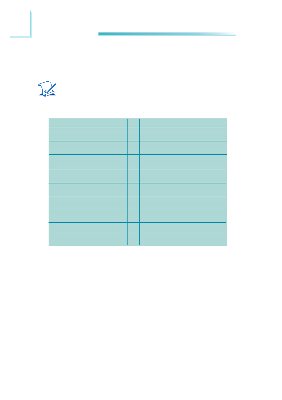
HD-LED
(Primary/Secondary IDE LED)
Reserved
ATX-SW
(ATX power switch)
Reserved
RESET
(Reset switch)
SPEAKER
(Speaker connector)
PWR-LED
(Power/Standby LED)
Pin Assignment
HDD LED Power
HDD
N. C.
N. C.
PWRBT+
PWRBT-
N. C.
N. C.
Ground
H/W Reset
Speaker Data
N. C.
Ground
Speaker Power
LED Power (+)
LED Power (+)
LED Power (-) or Standby Signal
Pin
3
5
14
16
8
10
18
20
7
9
13
15
17
19
2
4
6
- AR100-DR (112 pages)
- G7B630-N (127 pages)
- G7B630-N (154 pages)
- BT100 (71 pages)
- HR100-CRM (170 pages)
- BT103 (72 pages)
- BT161 (71 pages)
- CM100-C (70 pages)
- CD101-N (69 pages)
- CD102 Series (76 pages)
- CP100-NRM (150 pages)
- CR101-D (67 pages)
- CR100-CRM (177 pages)
- EL339-B (109 pages)
- G5C100-NR (160 pages)
- HD100-H81 (79 pages)
- HD101-H81 (83 pages)
- HD173-H81 (70 pages)
- HM100-QM87 (97 pages)
- HM103-QM87 (99 pages)
- HU103 (95 pages)
- KB161 (68 pages)
- HU173 (90 pages)
- LR100-N18M/N18S (126 pages)
- LR102-B18M (138 pages)
- EL630-NR (149 pages)
- NP101-D16C (150 pages)
- SB102-D (60 pages)
- NP102-N16C (144 pages)
- MB630-CRM (171 pages)
- SB630-CRM (184 pages)
- SB630-CRM (183 pages)
- SR100-L20C (144 pages)
- SR100-N (152 pages)
- LT600-L (149 pages)
- G7B630-N (147 pages)
- CA331-P (131 pages)
- EL330-DR (142 pages)
- CP337-NRM (174 pages)
- HD310-Q87 (101 pages)
- EL620-C (192 pages)
- G7L630-B (133 pages)
- HD330-H81 (81 pages)
- HD330-Q87 (85 pages)
- HD332-H81 (76 pages)