Hardware installation – DFI AM636-B User Manual
Page 22
22
2
Hardware Installation
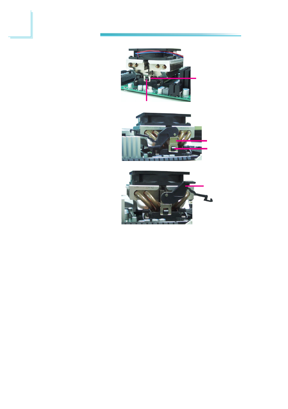
3. Place the heat sink on
top of the CPU. Now hook
the retention clips on both
sides of the heat sink onto
the retention module base
by fitting the hole(s) on the
retention clip into the re-
taining tab(s) of the reten-
tion module base.
Note:
• You will not be able to secure the fan and heat sink assembly in place if it
did not fit properly onto the retention module base.
• Make sure there is sufficient air circulation across the CPU fan and heat
sink.
5. Connect the CPU fan’s cable connector to the CPU fan connector on the sys-
tem board.
4. Move the retention lever to
its opposite side then push
it down to lock the fan and
heat sink assembly to the
retention module base.
Retention clip
Retaining tab
Retention clip
Retaining tab
Retention
lever
- AR100-DR (112 pages)
- G7B630-N (127 pages)
- G7B630-N (154 pages)
- BT100 (71 pages)
- HR100-CRM (170 pages)
- BT103 (72 pages)
- BT161 (71 pages)
- CM100-C (70 pages)
- CD101-N (69 pages)
- CD102 Series (76 pages)
- CP100-NRM (150 pages)
- CR101-D (67 pages)
- CR100-CRM (177 pages)
- EL339-B (109 pages)
- G5C100-NR (160 pages)
- HD100-H81 (79 pages)
- HD101-H81 (83 pages)
- HD173-H81 (70 pages)
- HM100-QM87 (97 pages)
- HM103-QM87 (99 pages)
- HU103 (95 pages)
- KB161 (68 pages)
- HU173 (90 pages)
- LR100-N18M/N18S (126 pages)
- LR102-B18M (138 pages)
- EL630-NR (149 pages)
- NP101-D16C (150 pages)
- SB102-D (60 pages)
- NP102-N16C (144 pages)
- MB630-CRM (171 pages)
- SB630-CRM (184 pages)
- SB630-CRM (183 pages)
- SR100-L20C (144 pages)
- SR100-N (152 pages)
- LT600-L (149 pages)
- G7B630-N (147 pages)
- CA331-P (131 pages)
- EL330-DR (142 pages)
- CP337-NRM (174 pages)
- HD310-Q87 (101 pages)
- EL620-C (192 pages)
- G7L630-B (133 pages)
- HD330-H81 (81 pages)
- HD330-Q87 (85 pages)
- HD332-H81 (76 pages)