6 sensor replacement – Daktronics GPR-12EV-RGB User Manual
Page 72
Temperature Sensor Mounting For
GalaxyPro Revolution Displays
page 4 of 4
terminate the temperature sensor from one display to the other.
Interconnect Locations – M4 Controller
Primary
(A31-TB1)
Field
Cabling
Secondary
(A31-TB1)
Pin 2 (GND CAN)
Black
Pin 2 (GND CAN)
Pin 3 (CAN H)
Green
Pin 3 (CAN H)
Pin 4 (CAN L)
White
Pin 4 (CAN L)
One end terminates at the 4-position terminal
block (TB1) on the primary display. The other
end terminates at the 4-position terminal block
(TB1) in the second display. Refer to Figure 6
and the following table for correct
interconnect locations.
Note: Do not connect the wire to pin one on either display.
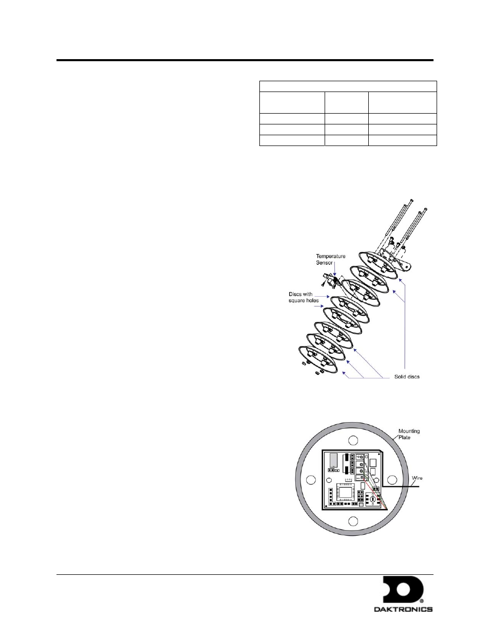
1.6 Sensor Replacement
If the temperature sensor board or wiring
malfunctions, access it by:
Figure 7: Temperature Sensor Diagram
1. Open the temperature sensor housing by
removing the four nuts from the bottom and
then removing the five bottom disks. Refer to
Figure 7 for details on sensor housing
disassembly.
2. Label the wires connected to the temperature
sensor board and then disconnect the cable
from the sensor terminal block in the
temperature sensor housing.
3. Remove the two screws holding the board to
the plastic disk. Install the new board and
replace the two screws.
4. Reconnect the cable to the temperature sensor board, making sure all the wires make a
good electrical connection.
Figure 8: Temperature Sensor Wiring
5. Route wires around the sensor board as shown
in Figure 8 and reassemble the sensor enclosure.
DD1514799 Rev 0
29 January 2009
201 Daktronics Drive PO Box 5128, Brookings, SD 57006-5128
tel: 866-343-3122 fax: 605-697-4700
www.daktronics.com