Multi-line controller replacement, Power supply replacement – Daktronics GPR-12EV-RGB User Manual
Page 34
28
Parts Replacement
Multi-Line Controller Replacement
Tools required:
5
/
16
” Nutdriver
1. Turn off power to the display.
2. Remove the module directly in front of the MLC. Typically, this is in the left side of
the display, approximately the third module from the bottom of the cabinet. Refer to
the appropriate Layout Drawing for exact location.
3. Remove enclosure cover.
4. Disconnect the fiber cables.
5. Remove all ribbon cables, and unplug the ISAC fan control, labeling the module
number as they are removed to insure proper replacement.
6. Remove the six nuts holding the board in place using a
5
/
16
” nut driver.
7. To install the new MLC, move it unit into place and replace the six nuts that hold it
to the display back. Reconnect fiber and ribbon cables, and plug the ISAC fan control
back in. Turn on power, observing the boot-up sequence. Note that the LEDs to the
right of the fiber cables are on; DS23 to the left of the fiber cable should be off. Refer
Power Supply Replacement
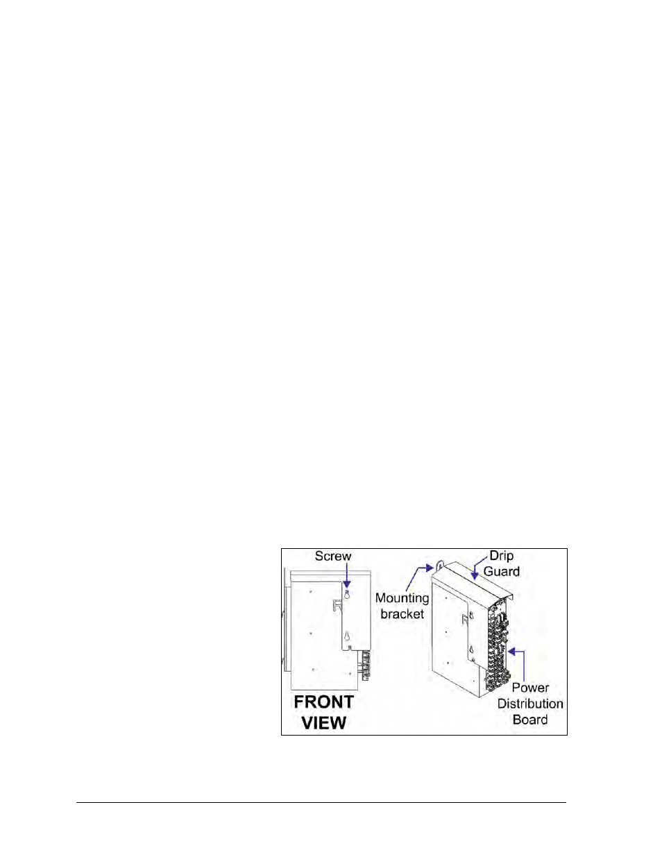
Power supplies, shown in Figure 28 and Figure 29, in GalaxyPro
®
Revolution displays
handle a range of power from 120 to 240 volt. The power supply contains a power
distribution board on one edge that receives AC power and then supplies DC power to
modules and other internal components. Each module is connected to a jack on the power
distribution board by an individual power cable.
Tool required: #2 Phillips screwdriver
1. Turn off power to the
display.
2. Remove the module
directly in front of the
appropriate power
supply.
3. Disconnect the
connectors from the
power source as well
as those going to the
modules, noting the
jack numbers going to
each module. Also,
unplug the ISAC fan
control.
Figure 28: Power Supply