Section 7: diagnostics and troubleshooting, 1 safety precautions, 2 controller diagnostics – Daktronics GPR-12EV-RGB User Manual
Page 27: Section 7, Diagnostics and troubleshooting, Safety precautions, Controller diagnostics
Diagnostics and Troubleshooting
21
Section 7:
Diagnostics and Troubleshooting
This section defines the diagnostic LEDs located on the controller, Multi-line Controller (MLC), and
temperature sensor. Troubleshooting tips are also provided for solving display problems.
7.1 Safety Precautions
Disconnect power when
servicing the display.
Do not modify the display
structure or attach any
panels or coverings to the
display without written
consent of Daktronics.
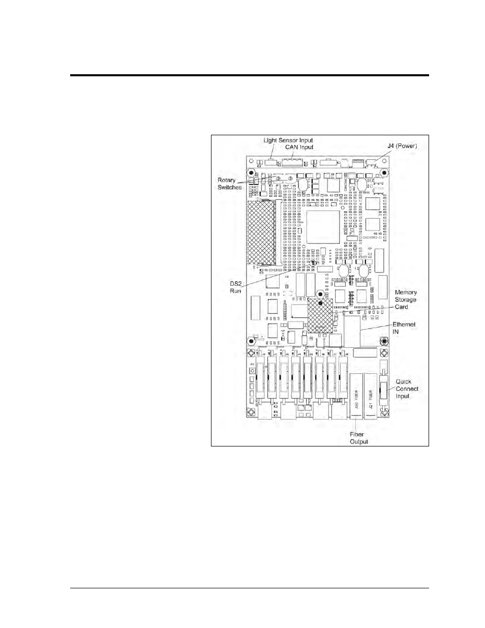
7.2 Controller
Diagnostics
The controller, shown in
Figure 22, receives
communication from the
computer and sends it to the
MLCs which output it to the
modules. The LEDs on the
controller show whether the
power and communication
signal are working properly.
One or two modules and the
controller enclosure cover
must be removed to access
the controller. Refer to
Section 6.2 for instructions
on how to access display
enclosure.
Remember to disconnect
power to the display before
accessing the interior. However, after removing the modules and wires are found to be safe,
power can be turned on to view the diagnostic LEDs.
A steady flash of about once per second on the DS2 “Run” LED indicates that the controller is
working properly. An increased flash rate indicates that the controller is booting.
Figure 22: Controller Component Locations